Table of Contents
Advertisement
Advertisement
Table of Contents

Related Manuals for Potter PFC-6006


Summary of Contents for Potter PFC-6006
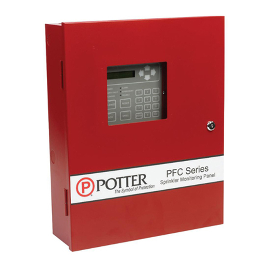
- Page 1 PFC-6006 Sprinkler Monitoring Panel Installation, Operation & Programming Manual Potter Electric Signal Company, LLC St. Louis, MO Customer Service: (866) 240-1870 • Technical Support: (866) 956-1211 • Fax: (314) 595-6999 www.pottersignal.com Manual #5403559–Rev D 11/17...
- Page 2 WARRANTY INFORMATION The essential purpose of any sale or contract for sale of any of the products listed in the POTTER catalog or price list is the furnishing of that product. It is expressly understood that in furnishing said product, POTTER does not agree to insure the Purchaser against any losses the Purchaser may incur, even if resulting from the malfunction of said product.
-
Page 3: Table Of Contents
PFC-6006 • 5403559 • REV D • 11/17 Table of Contents Section 1: Introduction ..........................1-1 Purpose of This Manual ..........................1-1 System Overview ............................1-1 System Features ............................1-1 P-Link Accessories ..........................1-1 How to Use this Manual .........................1-1 Common Terminology ..........................1-1 Section 2: Before You Start Installation ....................2-2 System Specifications ..........................2-2... - Page 4 PFC-6006 • 5403559 • REV D • 11/17 Canadian Events Display ........................4-18 Control Panel Menu Tree ........................4-20 Section 5: Programming ......................... 5-21 Programming Options ..........................5-21 Programming Overview ........................5-23 The Programming Cycle ........................5-23 Software Installation ..........................5-23 LEARN Programming ..........................5-24 Connecting the Computer and Panel .....................5-24 Transferring Data ..........................5-26...
- Page 5 PFC-6006 • 5403559 • REV D • 11/17 Input Circuit Functions ........................5-51 NAC Functions ..........................5-52 AUX Functions ..........................5-52 Adding Points to Zones ........................5-54 Group by Area ..........................5-56 Programming Points & Appliances .......................5-58 On-Board DACT ..........................5-58 Remote Annunciators ........................5-59 Section 6: IP Communication ........................ 6-60 IP Reporting Accounts ........................6-61...
- Page 6 PFC-6006 • 5403559 • REV D • 11/17 PFC-6006 Sprinkler Monitoring Panel Installation, Operation & Programming Manual...
-
Page 7: Section 1: Introduction
Section 1: Introduction The PFC-6006 Sprinkler Monitoring Panel is a compact, simple panel designed to monitor all facets of a wet or dry fire sprinkler system and communicate the status to a monitoring station. The PFC-6006 panel is a listed and approved microprocessor based sprinkler monitoring panel and complies with UL-864, ULC-S527, ULC-S524, ULC-S537, NFPA-70, and NFPA-72, and NYC Fire Department Certificate of Approval #6159 &... -
Page 8: Section 2: Before You Start Installation
PFC-6006 • 5403559 • REV D • 11/17 Section 2: Before You Start Installation This section addresses information that will help you in completing a successful installation, such as the PFC-6006 cabinet layout, specifications, and environmental considerations. System Specifications Cabinet Description Eighteen (18) gauge sheet steel with hinged, removable locked door Enclosure dimensions –... -
Page 9: Electrical Specifications
PFC-6006 • 5403559 • REV D • 11/17 Electrical Specifications Please refer to the table below for electrical specifications: Table 3: System Panel Electrical Specifications Panel # NAC Rating per NAC Notes Style and Class Inputs – Class A or B NAC –... -
Page 10: Wiring Types
PFC-6006 • 5403559 • REV D • 11/17 Wiring Types Wiring specifications must be followed to prevent damage or other consequences. Please refer to the wiring diagram below for proper wiring requirements. Figure 1. PFC-6006 Wire Routing Example Wire Routing for PFC-6006... -
Page 11: Cabinet Dimensions
Power Limited P-Link RS-485 Connections Low Voltage Power Limited Phone Line – DACT High Voltage Non-Power Limited AUX Power Low Voltage Power Limited Cabinet Dimensions Figure 2. PFC-6006 Main Board Module Shown Installed in Cabinet (shown with door removed) DWG #559-1... -
Page 12: Cabinet Mounting Instructions
PFC-6006 • 5403559 • REV D • 11/17 Figure 3. PFC-6006 Panel Showing Bezel Dimensions 14 1/4” (4) #6-32 X 1/4” 18 1/2” MACHINE SCREWS AND NUTS OPTIONAL TRIM DWG #559-2 DWG# 3503-8 Cabinet Mounting Instructions To mount the cabinet: The unit should be mounted in a convenient location, approximately 5 feet from the floor where it will be accessible for testing and servicing. -
Page 13: Cabinet Wiring Connections
PFC-6006 • 5403559 • REV D • 11/17 Cabinet Wiring Connections Figure 4. PFC-6006 Cabinet Wiring CAUTION: De-Energize Unit Prior to Servicing PFC-6006 120VAC 60Hz Sprinkler Monitoring Panel BLACK Connect to separate WHITE unswitched AC circuit GROUND Use 14 AWG or heavier gauge... -
Page 14: Battery Circuit Calculations
Door holders will contribute to standby current draw when AC is present. Total current must not exceed power supply rating (2A on PFC-6006). LED/Relay current must be accounted for in the battery calculation for the supplying source. -
Page 15: Main Supply Circuit
PFC-6006 • 5403559 • REV D • 11/17 Main Supply Circuit The AC terminals are located in the upper left hand portion of the main board. The main board supervises the main AC power and provides indication that the AC power is absent. The terminals are rated at 120 VAC 60 Hertz and are marked so accordingly on the board. -
Page 16: Section 3: Installation
Input Circuits There are six (6) programmable Input or Initiating Device Circuits (IDC) provided on the PFC-6006, which are the same as a conventional fire system input. They are supervised, and power limited to protect 2-wire smoke detectors. Input Circuit #1 may be wired for either Class A, Style D or Class B, Style B;... -
Page 17: Input Circuits #1-6 Class B, Style B Wiring Configuration
1. Maximum wiring resistance must not exceed 100 ohms. 2. The input has ground fault detection with 0 ohm impedance to ground. 3. The Potter part number for the listed end of line assembly is #3005013 EOL Resistor Asssembly. 3-11... -
Page 18: Notification Appliance Circuits Installation
Notification Appliance Circuits Installation There is one (1) NAC circuit provided on the PFC-6006 rated as continuous 0.5 amps at 24 VDC. The NAC circuit is configurable as Class B, Style Y only. (Please refer to the wiring example located in this section.) NAC Wiring Characteristics Output is supervised and regulated. -
Page 19: P-Link Points
PFC-6006 • 5403559 • REV D • 11/17 P-Link Points Accessory points, such as the RA-6075 or RA-6006 remote annunciator, are connected to the main control panel utilizing the four-wire P-Link bus for power and communication. This panel supports a maximum of four (4) P-Link points, which can be connected using a Class B, Style 4 wiring style. -
Page 20: P-Link Addresses
PFC-6006 • 5403559 • REV D • 11/17 P-Link Addresses Every P-Link device has a five position dip switch which is used to program the device address ranging from one (1) to thirty-one (31). Use the chart below to reference Dip Switch Settings:... -
Page 21: Dact Connection
The DACT communicates using the SIA-DCS or Ademco Contact ID protocols. The DACT is selectable and fully programmable. The PFC-6006 automatically monitors each phone line for voltage and has the ability to seize the line and connect with a remote receiver. Once the communication is complete, the DACT will hang up the phone line. -
Page 22: Section 4: Operation
PFC-6006 • 5403559 • REV D • 11/17 Section 4: Operation This section provides an overview of the control panel’s basic operations, which includes the status LEDs, function pushbuttons, and a Control Panel Menu Tree quick reference sheet. Control Panel Basic Operation The control panel is comprised of a two (2) line x 16-character LCD display panel, arrow keys, push button function keys, status LEDS, and the numeric keypad. -
Page 23: Menu Navigation Keys
PFC-6006 • 5403559 • REV D • 11/17 Menu Navigation Keys The arrow keys allow you to scroll or move through the control panel menus. The Enter and Esc keys may also be used to navigate through menus; they are located on the numeric keypad. The table shown below provides a summary of the navigation keys. -
Page 24: Status Leds
PFC-6006 • 5403559 • REV D • 11/17 Status LEDs The control panel’s LEDs communicate system conditions by illuminating and/or flashing the applicable green, red or amber indicators. These are described in the table below. Figure 17. Control Panel Status LEDs... - Page 25 PFC-6006 • 5403559 • REV D • 11/17 The panel events display according to the priority of the event. As additional events of a higher priority occur, the display automatically adjusts to show the highest priority event first, then moves lower priority events to the right and/or wraps down to the 2nd line.
-
Page 26: Control Panel Menu Tree
PFC-6006 • 5403559 • REV D • 11/17 Control Panel Menu Tree This section provides a reference to menu options as they appear on the LCD panel. Appendix G also provides a copy of the menu tree. MAIN MENU 1=View History... -
Page 27: Section 5: Programming
PFC-6006 • 5403559 • REV D • 11/17 Section 5: Programming This section addresses programming options and their parameters, provides an overview of the programming process, and addresses how to use the two programming methods: (1) the LEARN function, and (2) the remote computer programming process. - Page 28 PFC-6006 • 5403559 • REV D • 11/17 Table 10: Programming Options Feature or Permitted Setting(s) Permitted Topic Possible Settings Comment Option in UL (Y/N) in UL864? Zone Silenceable Yes/No All settings allowed Option is not allowed Zone Silence Inhibit...
-
Page 29: Programming Overview
Note: This approach may eliminate programming errors, however, these are only recommendations. Software Installation It's easy to install the PFC-6006 software and requires only a few minutes to complete. Once done, the program automatically creates a shortcut icon on your desktop for easy access. -
Page 30: Learn Programming
PFC-6006 • 5403559 • REV D • 11/17 LEARN Programming The LEARN mode enables you to efficiently configure all connected, addressed Remote Annunciators. Only authorized users may access this function. LEARN generates a list of all remote annunciators, which may be viewed on a remote computer. - Page 31 PFC-6006 • 5403559 • REV D • 11/17 The following series of messages display on the LCD: PFC-6006 Initializing IP PFC-6006 Obtaining IP Notes: If the Ethernet cable is connected to PC, you will see the "Initializing IP" message prior to the "Obtaining IP"...
-
Page 32: Transferring Data
PFC-6006 • 5403559 • REV D • 11/17 Transferring Data This section provides step-by-step instructions for completing uploading and downloading data transfers. The "Transfer" icons are located at the top of the Programmer window and are briefly described below. Table 11: Transfer Functions... -
Page 33: Uploading From Panel To Computer
PFC-6006 • 5403559 • REV D • 11/17 Uploading from Panel to Computer The Upload Configuration File to Computer transfer icon is used to upload the configuration file from the panel to the computer once the LEARN function is completed or whenever points are added or removed from the panel. -
Page 34: Downloading Configuration File To Panel
PFC-6006 • 5403559 • REV D • 11/17 Enter IP address or panel name in the “Transfer Via IP” field. Notes: • To capture your panel’s unique IP address, disconnect the Ethernet cable from panel. The message “Ethernet Lost” displays indicating connectivity is lost. Be prepared to write down the address, and reconnect cable. -
Page 35: File New
PFC-6006 • 5403559 • REV D • 11/17 File New The File New menu option is used to complete all programming from scratch on the computer. You must select the correct panel model prior to programming. Note: It is imperative that you choose the correct panel model prior to programming or completing any data transfers, otherwise, you cannot complete a successful download to the panel. - Page 36 PFC-6006 • 5403559 • REV D • 11/17 Downloading a Configuration File To download the configuration file: Click the Download Configuration File to Panel icon or right click from the “Transfers” region, then click “Add”. The Transfer dialog box displays.
-
Page 37: Uploading History Events Status Reports
PFC-6006 • 5403559 • REV D • 11/17 Uploading History Events Status Reports The Upload History File to Computer icon allow you to view valuable information that can be essential when analyzing system operations. You may choose to print the History reports by using the Print icon; reports can be scheduled to be automatically sent to authorized e-mail addresses. -
Page 38: Printing Reports
PFC-6006 • 5403559 • REV D • 11/17 Printing Reports The Print icon allows you to print History reports. Double-click the History file listed in the Transfer window prior to clicking the Print icon. An example of the Report window, which displays a History report, is shown below: Figure 32. -
Page 39: Panel Software Overview
PFC-6006 • 5403559 • REV D • 11/17 Panel Software Overview This section gives you an overview of the Panel Configuration Software. It addresses navigating through the program windows, understanding the purpose of icons and program features, using Window’s conventional editing techniques and other program shortcuts to efficiently configure your system. -
Page 40: Program Icons
PFC-6006 • 5403559 • REV D • 11/17 Program Icons The panel software uses several standard Windows’ icons, such as the close button and scroll bars. There are others that are unique to the panel software, such as auto hide, and window position which are summarized in the table below:... -
Page 41: Programming Functions Overview
PFC-6006 • 5403559 • REV D • 11/17 Programming Functions Overview The table below gives you a snapshot of the menu order along with a brief description of each. Details for these options are provided on the following pages. Table 13: Programming Menu Overview... -
Page 42: Remote Access Code
Figure 36. Example of the Panel Configuration Screen User Name / Password The default user name and password is “Potter” as shown below; they can be changed to ensure that only authorized personnel can transfer data to and from the panel. -
Page 43: General System Functions
PFC-6006 • 5403559 • REV D • 11/17 General System Functions Job Details Site specific information, such as company name, address and phone numbers may be entered in this window. This information is stored in the panel and is used to identify the panel when using e-mail reporting options. Please refer to the figure shown below. -
Page 44: Users
PFC-6006 • 5403559 • REV D • 11/17 Users The Users option allows you to create up to ten (10) user profiles, if needed. Each profile may have different access rights, which controls the panel functions a user may access. -
Page 45: System E-Mail Functions
“panel serial number". The serial number is the same as the NetBIOS name, and is located on the panel as shown below. Note: Outgoing panel e-mails are routed through a dedicated Potter server. You must make a notation of your panel's outgoing e-mail address in order to send e-mail requests remotely. -
Page 46: P-Link E-Mail Notification Requirements
PFC-6006 • 5403559 • REV D • 11/17 System e-mail communications and functions are intended for informational reporting purposes only. They are intended to be used as a convenience function. E-mail communications should NOT be used as a primary means of reporting emergency information. -
Page 47: E-Mail Sent From Panel
PFC-6006 • 5403559 • REV D • 11/17 System e-mail communications and functions are intended for informational reporting purposes only. They are intended to be used as a convenience function. E-mail communications should NOT be used as a primary means of reporting emergency information. -
Page 48: E-Mail Report Requested From Pc
PFC-6006 • 5403559 • REV D • 11/17 System e-mail communications and functions are intended for informational reporting purposes only. They are intended to be used as a convenience function. E-mail communications should NOT be used as a primary means of reporting emergency information. - Page 49 PFC-6006 • 5403559 • REV D • 11/17 System e-mail communications and functions are intended for informational reporting purposes only. They are intended to be used as a convenience function. E-mail communications should NOT be used as a primary means of reporting emergency information.
-
Page 50: Receiving E-Mail Status Reports
PFC-6006 • 5403559 • REV D • 11/17 System e-mail communications and functions are intended for informational reporting purposes only. They are intended to be used as a convenience function. E-mail communications should NOT be used as a primary means of reporting emergency information. -
Page 51: Creating E-Mail Reminders
PFC-6006 • 5403559 • REV D • 11/17 System e-mail communications and functions are intended for informational reporting purposes only. They are intended to be used as a convenience function. E-mail communications should NOT be used as a primary means of reporting emergency information. -
Page 52: System Programming
PFC-6006 • 5403559 • REV D • 11/17 System Programming System programming involves defining the function of points and their relationships to each other, referred to as "mapping". You can define behavior characteristics of individual or groups of points, map points into zones, and further customize your system using the panel configuration software from a computer. -
Page 53: Mapping Terminology
PFC-6006 • 5403559 • REV D • 11/17 Mapping Terminology The table below provides mapping terms that may be helpful to you in understanding the mapping concept: Table 16: Mapping Terminology Term Definition Mapping Creating relationships between points, modules and sensors and defining their behavior. -
Page 54: Zone Attributes
PFC-6006 • 5403559 • REV D • 11/17 Zone Attributes Zone attributes are the settings that control the overall behavior of points within the zone. The zone may be configured as latching or non-latching, silenceable vs. non-silenceable, among other attributes. -
Page 55: Creating Zones
PFC-6006 • 5403559 • REV D • 11/17 Table 18: Zone Attributes Attribute Description Silence-Inhibit Timer Default = 0 minutes Defines the amount of time you may not silence an output when in alarm. Range = 0 – 60 minutes... -
Page 56: Configuring Zones
PFC-6006 • 5403559 • REV D • 11/17 6. Go to the “Zone Configuration” window, to view all available zones. Figure 56. Example of Configuring Multiple Zones Configuring Zones The next step is to customize a zone’s attributes, which includes changing the name, selecting type of zone, and other characteristics (i.e., constant, double time output pattern, latching or non-latching, silenceable, auto-silence timer, etc.). -
Page 57: Input Circuit Functions
PFC-6006 • 5403559 • REV D • 11/17 Input Circuit Functions The IDC's ("Conventional Inputs") default to specific functions as shown in the 2nd table below; however, they may be reconfigured and renamed, based on the following configuration functions: Table 19: Input Circuit Functions... -
Page 58: Nac Functions
PFC-6006 • 5403559 • REV D • 11/17 NAC Functions The on-board NAC circuit (NAC 1) is automatically configured as “Conv NAC General Purpose”, but may be reconfigured to other functions, as described in the table below: Table 21: NAC Circuit Configuration Functions... - Page 59 PFC-6006 • 5403559 • REV D • 11/17 To configure a single point: Click on the Points function to display the "Points Configuration" window. Figure 58. Example of a Configuration Window Showing Conventional Input Functions Notes: •y Points are listed by device addresses automatically. You may sort points by clicking on the column or field name, i.e., "Name", "Function", or "Supervisory".
-
Page 60: Adding Points To Zones
PFC-6006 • 5403559 • REV D • 11/17 To configure a range of points: 1. Click the first point to configure from the “Function” field. 2. Press and hold the SHIFT key, then click in “Function” field of last point. - Page 61 PFC-6006 • 5403559 • REV D • 11/17 Drag and drop selected points from the Points' window to the “Device” window. The selected points display in the “Device” window, as shown below. Figure 62. Example of Configuring Multiple Points into Multiple Zones Points 4, 6 &...
-
Page 62: Group By Area
PFC-6006 • 5403559 • REV D • 11/17 Group by Area You may group information by different fields in many of the program windows. This flexibility is helpful when configuring or viewing a large amount of information, such as all points, zones or remote annunciators. Examples are included for illustration purposes only. - Page 63 PFC-6006 • 5403559 • REV D • 11/17 4. Click “+” next to the function to view a complete list of points. Click “-” to collapse list of points, as needed. Figure 67. Example of Expanded List of Grouped Points Note: Click “–”...
-
Page 64: Programming Points & Appliances
PFC-6006 • 5403559 • REV D • 11/17 Programming Points & Appliances This section addresses how to program the P-Link appliances and points, including the on-board DACT, and the RA-6075 or RA-6006 annunciators. On-Board DACT Each system has a built-in DACT or Digital Alarm Communicator Transmitter. The DACT provides notification to a remote monitoring company when alarms, troubles and supervisory conditions occur. -
Page 65: Remote Annunciators
PFC-6006 • 5403559 • REV D • 11/17 Remote Annunciators The PFC-6006 supports up to four (4) RA-6075 or RA-6006 remote annunciators. To add and configure a remote annunciator: Select Annunciators from system panel. Click the Add Device button to display the "Add Device” window. -
Page 66: Section 6: Ip Communication
PFC-6006 • 5403559 • REV D • 11/17 Section 6: IP Communication The system's built-in, on-board IP Communicator provides notification to a remote monitoring company when alarms, troubles, and supervisory conditions occur. The IP Communicator is used with an IP capable Sur-Guard receiver by means of the Fibro protocol. -
Page 67: Ip Reporting Accounts
PFC-6006 • 5403559 • REV D • 11/17 IP Reporting Accounts The "IP Reporting Accounts" section is used to program the IP Communicator operations and to customize the format of the reporting accounts. You may choose different settings for Alarms, Troubles and Supervisory conditions. Up to five (5) primary or secondary accounts may be configured. - Page 68 PFC-6006 • 5403559 • REV D • 11/17 Click on the Primary / Secondary Account Settings expand ellipsis icon to display additional setup options, as shown below: Figure 73. Example of Primary Account Settings "Expanded" Window Notes: – Use the scroll bar to display additional fields if not shown on right.
-
Page 69: Section 7: Appendices
Appendix A – Basic Operating Instructions These instructions must be framed and displayed next to the PFC-6006 panel in accordance with NFPA 72 fire code for Local Protected Fire Alarm Systems or ULC Standard CAN/ULC-S524. Test the system in accordance to NFPA 72 or CAN/ULC-S524. - Page 70 PFC-6006 • 5403559 • REV D • 11/17 Table 24: Operating Instructions Operation Task •y Press ENTER – Main Menu. •y Press 3 – Set Date / Time. Set Date / Time •y Use keypad to enter correct date; use right arrow to move through date field and to display time field.
-
Page 71: Appendix B - Modem Connectivity Setup
PFC-6006 • 5403559 • REV D • 11/17 Appendix B – Modem Connectivity Setup If your computer uses a modem for connectivity to the panel, choose the Options – Communications menu option. Next, select “Modem” as the transfer medium, and specify the modem com port. In rare instances, a modem may also require an initialization string. -
Page 72: Appendix C - System Maintenance And Testing
ULC-S524 to verify compliance with the applicable standards. Testing should be conducted by Potter factory trained fire alarm technician(s) in the presence of a representative of the Authority Having Jurisdiction (AHJ) and the building owners representative. Refer to NFPA 72 (National Fire Alarm Code), Inspection Testing and Maintenance or ULC-S536, Canadian Building and Electrical codes. -
Page 73: Replacement And Testing Recommendations
PFC-6006 • 5403559 • REV D • 11/17 Replacement and Testing Recommendations The batteries are to be replaced at least once every four years or more frequently if specified by local AHJ and manufacturer recommendations. Batteries should be dated at the installation. Minimal replacement battery capacity displays on the control panel marking label. -
Page 74: Appendix D - Compatible Points Table
PFC-6006 • 5403559 • REV D • 11/17 Appendix D – Compatible Points Table This section provides a listing of all NAC appliances, two-wire (2-wire) smoke detectors, the built-in DACT and remote annunciator device compatibilities. Table 25: Device Compatibilities Module/Device... -
Page 75: Appendix E - Compatible Smoke Detectors Table
PFC-6006 • 5403559 • REV D • 11/17 Appendix E – Compatible Smoke Detectors Table Table 26: Smoke Detector Compatibilities Detector Model Identifier Base Model Identifier SYSTEM SENSOR (Brk) (Max. No. Of Detectors Per Zone Is 20) 1400* 2400* 2400TH*... - Page 76 PFC-6006 • 5403559 • REV D • 11/17 Detector Model Identifier Base Model Identifier SOC-24V HD-3 HSB-221 HB-54 NS6-221 HB-4 NS4-221 HB-4 NS6-220 HB-3 SOC-24VN HD-3 HSB-221 HB-54 NS6-221 HB-4 NS4-221 HB-4 NS6-220 HB-3 FENWAL (Max. No. Of Detectors Per Zone Is 25)
-
Page 77: Appendix F - Compatible Auxiliary Circuit Devices
1430213 DH24120GB2 Ground mount, double door, plated, brass 1430214 DH24120GPD2 Ground mount, double door, powder coated, dark bronze Flow Switches (UL listed devices by Potter Electric Signal Company, LLC) 1116102 VSR-AT 2 Inch Auto Test 1116103 VSR-AT 3 Inch Auto Test... -
Page 78: Appendix G - Control Panel Menu
PFC-6006 • 5403559 • REV D • 11/17 Appendix G – Control Panel Menu MAIN MENU 1=View History 3=Set Date/Time 4=Walk Test 2=Enable/Disable 2=By Zone 1=By Point Select Device Zone _ _ _ _ 1=Disable Inputs Internal PWR (Enter Zone #... - Page 79 PFC-6006 Sprinkler Monitoring Panel Fire Panel Operating Instructions Normal Standby The green AC POWER LED will be illuminated and the user defined message on the LCD will be displayed. If the AC power is removed for more than 5 seconds, the green AC power LED will extinguish.
- Page 80 • For an in-depth overview of programming the DACT, view our on-line training video located at Potter's website as follows: www.pottersignal.com, Fire Alarm Systems – Training, select Go to Training videos. Next, click the Additional Fire Training button and scroll to the PFC-6006 DACT video.
- Page 81 PFC-6006 • 5403559 • REV D • 11/17 KEYPAD STEPS PANEL MENU OPTIONS Setup Phone Lines 1 & 2: Line's Default = Enabled. (The DACT can access the telephone line.) DACT Setup 3. Press Enter or "1" – Line1 Setup.
- Page 82 PFC-6006 • 5403559 • REV D • 11/17 KEYPAD STEPS PANEL MENU OPTIONS 10. Press ESC when all information has been [Press ESC to display the "DACT Setup" menu.] Dial Tone completed for Line 1. E x i t 11. Scroll to "Line2 Setup" and Enter.
- Page 83 PFC-6006 • 5403559 • REV D • 11/17 KEYPAD STEPS PANEL MENU OPTIONS 19. Enter "7" – Sec Acct ID, and enter the 6 = Pri Rpt Test secondary account ID provided by your 7 = Sec Acct ID central station.
Need help?
Do you have a question about the PFC-6006 and is the answer not in the manual?
Questions and answers