
Related Manuals for Vemer ADR Series


Summary of Contents for Vemer ADR Series
- Page 1 Analizzatore di Rete Manuale d’Uso Network Analyser User’s Manual Network Analyser User’s Manual...
-
Page 3: Table Of Contents
Index Safety warnings Page Technical specifications Page Instrument description Page Keys Page Parameter settings Page Measurement page display Page Measurement / calculation methods Page Serial communications Page ADR-View software Page Reference standards Page Dimensions and connection diagrams Page - 23 - ADR Network analyser - User’s guide... -
Page 4: Safety Warnings
7) Do not power or connect the instrument if any part of it is damaged NOTE: • VEMER mains analysers are designed to be used in locations with over-voltage category III and pollution level 2, in accordance with the EN 61010-1 standard •... -
Page 5: Instrument Description
• TV selected: primary 1÷9999 V, secondary 230 V • TA selected: primary 1÷9999 A, secondary 5 A • Serial output: insulated RS-485 with MODBUS RTU protocol (max 9600 Baud) for the ADR-R, ADR-D, ADR-R E and ADR-D E models •... -
Page 6: Keys
KEYS Scroll to the next page and set parameters Scroll to the previous page and set parameters Display of the system values • For the ADR-D, ADR-R, ADR-D E and ADR-R E: Display of the peak value and selection of parameters during programming •... - Page 7 TV setting VOLTAGE VOLTAGE • Press the “up” ( ) or “down” ( ) keys to select the required value of the flashing figure • To move to the next figure, press the “pK” key (or the (•) key in the spot version) •...
- Page 8 • Setting the serial port speed: press “pK” to select one of the 4 possible speeds (1200, 2400, 4800 or 9600 Baud). • To confirm the value set and move to the next window, press “T”. • Setting the parity bit: press “pK” to select one of the options, NONE, ODD or EVEN, in order.
- Page 9 Zeroing the reactive energy meter REACTIVE REACTIVE ENERGY ENERGY • Same procedure as the zeroing of the active energy meter. Rear lighting handling • Press “pK” (or (•) in the spot version) to select from the options “NO” (rear lighting off), “YES” (on) or “TIME” (on for approximately 60 seconds after a key is pressed).
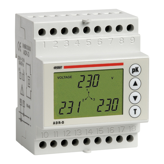
- Page 10 DISPLAYING THE MEASUREMENT PAGE When the instrument is switched on (or after the programming procedure) the main page is displayed after approximately 3 seconds when the display is fully operational. When “up” ( ) is pressed from the main page, the following are displayed: all the other measurement pages in sequence.
- Page 11 VOLTAGE VOLTAGE VOLTAGE - the instant when the peak occurred (time and date) - the number of hours lapsing between the start-up of the instrument and the occurrence of the peak (expressed in hours and tenths of an hour) • To zero the peak values, simply press “pK” and “T” at the same time •...
- Page 12 4a) Peak phase current value page (not in the spot version) CURRENT CURRENT CURRENT • The same procedure as that for the display of the peak phase voltage values 5) Active phase power page POWER POWER ACTIVE ACTIVE • The active phase powers are displayed. •...
- Page 13 6) Apparent phase power page POWER POWER APPARENT APPARENT • The apparent phase powers are displayed • The “T” key is used to display the apparent system power. 7) Reactive phase power page POWER POWER REACTIVE REACTIVE • The reactive phase powers are displayed. •...
- Page 14 8) Phase power factor page cos cos • The phase power factors are displayed • The “T” key is used to display the system power factor 9) Voltage-current phase shift page • The voltage-current phase shifts are displayed in sexagesimal degrees (the letter “C”...
- Page 15 11) Total reactive energy page VARh VARh REACTIVE REACTIVE ENERGY ENERGY • The total reactive energy is displayed • The “T” key is used to display the partial reactive energy readings for the single phases (these energy readings are zeroed each time the total reactive energy is increased) 12) Frequency page •...
-
Page 16: Measurement / Calculation Methods
13a) Setting the time and date (not in the spot version) • When “T” is pressed from one of the time display pages, the time and date can be • Press the “up” ( ) or “down” ( ) keys to select the required value of the flashing number •... -
Page 17: Serial Communications
E = E 1 +E 2 +E 3 Total active energy Er = Er 1 +Er 2 +Er 3 Total reactive energy SERIAL COMMUNICATION (not in the spot version) The instrument has an insulated RS-485 serial output The data communication system is based on the MODBUS protocol and is suitable for the connection of the following to a master device such as a PC or PLC in a common RS-485 line: •... -
Page 18: Reference Standards
REFERENCE STANDARDS ■ Conformity to EC directives 2006/95/EC (LVD) 2004/108/EC (EMC) is declared with reference to the following harmonised standards: ■ Safety: EN 61010-1 ■ Electromagnetic compatibility: EN 61000-6-2 and EN 61000-6-4 ■ Metering requirements: EN 62052-21 and EN 62053-23 - 38 - ADR Network analyser - User’s guide... - Page 19 DIMENSIONS VOLTAGE GMk Wh Hz VARh CURRENT cos FREQUENCY POWER APPARENT REACTIVE ENERGY ADR-R - 39 - ADR Network analyser - User’s guide...
- Page 20 CONNECTION DIAGRAMS ADR-R ADR-R E RS-485 Single phase ADR-R ADR-R E RS-485 Three phase ADR-R ADR-R E RS-485 Three phase+N Attention: the secondary circuits of the CT can be earthed for the ADR-R model only - 40 - ADR Network analyser - User’s guide...
- Page 21 CONNECTION DIAGRAMS ADR-R spot ADR-R E spot Single phase ADR-R spot ADR-R E spot Three phase ADR-R spot ADR-R E spot Three phase+N Attention: the secondary circuits of the CT can be earthed for the ADR-R spot model only - 41 - ADR Network analyser - User’s guide...
- Page 22 DIMENSIONS DIMENSIONS VOLTAGE GMk Wh Hz VARh CURRENT cos FREQUENCY POWER APPARENT REACTIVE ENERGY 10 11 12 13 14 15 16 17 18 - 42 - ADR Network analyser - User’s guide...
- Page 23 CONNECTION DIAGRAMS ADR-D ADR-D E RS-485 Single phase ADR-D ADR-D E RS-485 Three phase ADR-D ADR-D E RS-485 Three phase+N Attention: the secondary circuits of the CT can be earthed for the ADR-D model only - 43 - ADR Network analyser - User’s guide...
- Page 24 CONNECTION DIAGRAMS ADR-D spot ADR-D E spot Single phase ADR-D spot ADR-D E spot Three phase ADR-D spot ADR-D E spot Three phase+N Attention: the secondary circuits of the CT can be earthed for the ADR-D spot model only - 44 - ADR Network analyser - User’s guide...
- Page 25 Vemer S.p.A. I - 32032 Feltre (BL) Via Camp Lonc, 16 Tel +39 0439 80638 Fax +39 0439 80619 e-mail: info@vemer.it - web site: www.vemer.it...
Need help?
Do you have a question about the ADR Series and is the answer not in the manual?
Questions and answers