Advertisement
Table of Contents
Operating and
Installation
Instructions
Read and observe these Oper-
ating and Installation Instruc-
tions!
KNF Neuberger GmbH
Alter Weg 3
D-79112 Freiburg
Germany
Phone +49-(0)7664-5909-0
Fax
+49-(0)7664-5909-99
E-mail: info@knf.de
www.knf.de
KNF 121610-121613 07/16
Translation of original Operating and Installation Instructions, english
Diaphragm-Gas Sampling Pumps
with double diaphragm System
N 143 AN.12 E
N 143 AV.12 E
N 186.1.2 AN.12 E
N 186.1.2 AV.12 E
N 186.3 AN.12 E
N 186.3 AV.12 E
Contents
1. About this document ................................................................. 2
2. Use ........................................................................................... 3
3. Safety ....................................................................................... 5
4. Technical Data.......................................................................... 7
5. Design and function ................................................................ 11
6. Installation and connection ..................................................... 14
7. Operation ................................................................................ 18
8. Servicing ................................................................................. 20
9. Troubleshooting ...................................................................... 25
10. Spare parts and accessories .................................................. 27
11. Returns ................................................................................... 28
N 143 SN.12 E
N 143 SV.12 E
N 186.1.2 SN.12 E
N 186.1.2 SV.12 E
N 186.3 SN.12 E
N 186.3 SV.12 E
Keep for future use!
Page
Advertisement
Table of Contents

Related Manuals for KNF N 143 AV.12 E


Summary of Contents for KNF N 143 AV.12 E
-
Page 1: Table Of Contents
Diaphragm-Gas Sampling Pumps with double diaphragm System N 143 AN.12 E N 143 SN.12 E N 143 AV.12 E N 143 SV.12 E Operating and Installation Instructions Read and observe these Oper- ating and Installation Instruc- tions! N 186.1.2 AN.12 E N 186.1.2 SN.12 E... -
Page 2: About This Document
An activity to be carried out (a step) is specified here. 1. The first step of an activity to be carried out is specified here. Additional, consecutively numbered steps follow. This symbol refers to important information. Translation of original Operating and Installation Instructions, english, KNF 121610-121613 07/16... -
Page 3: Use
If pressure or flow rate change without apparent reason, immediately switch off the pump and check for damages. Only transfer gases which remain stable under the pressures and temperatures occurring in the pump. Translation of original Operating and Installation Instructions, english, KNF 121610-121613 07/16... - Page 4 An overpressure must not be applied to the suction side of the pump. Pumps with three-phase motor are not provided for the operation with frequency converter. Translation of original Operating and Installation Instructions, english, KNF 121610-121613 07/16...
-
Page 5: Safety
For the purposes of the Machinery Directive 2006/42/EC, pumps are “partly completed machinery,” and are therefore to be regarded as not ready for use. Partly completed machinery may not be Translation of original Operating and Installation Instructions, english, KNF 121610-121613 07/16... - Page 6 DIN EN 61000-3-2/3 DIN EN 60204-1 Customer service and Only have repairs to the pumps carried out by the KNF Customer repairs Service responsible. Use only genuine parts from KNF for servicing work. Translation of original Operating and Installation Instructions, english, KNF 121610-121613 07/16...
-
Page 7: Technical Data
N 186.3 SN.12 E Assembly Material Head plate, intermediate plate, Stainless Steel Intermediate ring Aluminium Working diaphragm Safety diaphragm Valve plate Retainer plate Stainless Steel Conrod disc Aluminium O-rings Tab. 4 Translation of original Operating and Installation Instructions, english, KNF 121610-121613 07/16... - Page 8 N 186.3 SV.12 E Parameter Value Max. permissible operating pressure [bar g] Ultimate vacuum [mbar abs.] Delivery rate at atm. pressure [l/min]* Tab. 8 *Liters in standard state (1,013 mbar) Translation of original Operating and Installation Instructions, english, KNF 121610-121613 07/16...
- Page 9 N 186.1.2 SN.12 E approx. 23.0 N 186.1.2 SV.12 E N 186.3 AN.12 E approx. 18.0 N 186.3 AV.12 E N 186.3 SN.12 E approx. 23.5 N 186.3 SV.12 E Tab. 11 Translation of original Operating and Installation Instructions, english, KNF 121610-121613 07/16...
- Page 10 Refer to chapter 5 for an explanation of purpose and prin- ciple. Refer to chapter 6.4 for notes on assembly and connec- tion. Refer to chapter 7 for notes on operation. Translation of original Operating and Installation Instructions, english, KNF 121610-121613 07/16...
-
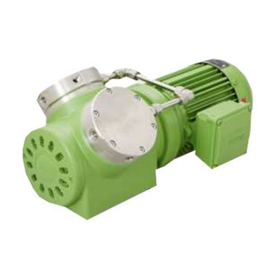
Page 11: Design And Function
2 (2x) Pneumatic head connection pressure side Fan cover Union nut Motor Fig. 2: Double diaphragm pump N 186.1.2__.12 E Translation of original Operating and Installation Instructions, english, KNF 121610-121613 07/16... - Page 12 (10) by the working diaphragm and a safety diaphragm. A second diaphragm (safety diaphragm (7)) is located underneath the working diaphragm. This second diaphragm is under less Translation of original Operating and Installation Instructions, english, KNF 121610-121613 07/16...
- Page 13 The innerspace (5) between both diaphragms can be pressure monitored so that any damage to the working diaphragm will be noted immediately. For this purpose, the pump head has two holes (6). Translation of original Operating and Installation Instructions, english, KNF 121610-121613 07/16...
-
Page 14: Installation And Connection
N 186.3 __.12 E; shown without pneumatic connections (All dimensional tolerances conform to DIN ISO 2768-1, Tolerance Class V) Install the pump so that the motor fan can intake sufficient Cooling air supply cooling air. Translation of original Operating and Installation Instructions, english, KNF 121610-121613 07/16... - Page 15 2. Open terminal box cover. 3. All pumps except versions with 3 phase motor: Connect the mains cables to the connections L1 and N of the pump motor. Translation of original Operating and Installation Instructions, english, KNF 121610-121613 07/16...
- Page 16 2. Connect the suction line and pressure line (see chapter 4, table 9 for the mounting dimensions). 3. Lay the suction and pressure line at a downward angle to prevent condensate from running into the pump. Translation of original Operating and Installation Instructions, english, KNF 121610-121613 07/16...
- Page 17 Immediately stop the pump if the working dia- phragm ruptures. The working diaphragm and the safety diaphragm must be replaced before continuing with operation (see chapter 8, Maintenance). Translation of original Operating and Installation Instructions, english, KNF 121610-121613 07/16...
-
Page 18: Operation
For further information, contact our technical adviser (see front page for telephone number). Translation of original Operating and Installation Instructions, english, KNF 121610-121613 07/16... - Page 19 KNF recommends: When transferring aggressive media, flush the pump prior to switch-off (see chapter 8.2.1) to increase the service life of the diaphragm. Translation of original Operating and Installation Instructions, english, KNF 121610-121613 07/16...
-
Page 20: Servicing
Always replace the safety diaphragm at the same time the working diaphragm is replaced. Always replace working diaphragm and safety diaphragm together to maintain performance and safety of the pump. Translation of original Operating and Installation Instructions, english, KNF 121610-121613 07/16... - Page 21 Retaining clips for assembling of intermediate ring, intermediate plate and head plate (see „Assembling“, steps 4, 10 and 13) Felt-tip pen Tab. 15 * according to accessories list, chapter 10 Translation of original Operating and Installation Instructions, english, KNF 121610-121613 07/16...
- Page 22 Undo the screws that hold the fan cover. For one-headed pumps: Fig. 1/7, p. 11; for two-headed pumps: Fig. 2/7, p. 11 or Fig. 3/7, p. 12 and remove the fan cover. Translation of original Operating and Installation Instructions, english, KNF 121610-121613 07/16...
- Page 23 (A); now place intermediate ring (B) on the housing (A) according to the marks made previously; tight- en the screws (M) lightly. 6. Now remove the retaining clips, and tighten the screws (M) diagonally hand-tight. Translation of original Operating and Installation Instructions, english, KNF 121610-121613 07/16...
- Page 24 21. Check and ensure the gas-tightness of the pump head/pump heads and the tubing: Before putting the pump into operation again, check and ensure the gas-tightness of the pump head and the tubing. WARNING Translation of original Operating and Installation Instructions, english, KNF 121610-121613 07/16...
-
Page 25: Troubleshooting
Pneumatic lines or connection parts have an insufficient cross Eliminate throttling (e.g. valve) if necessary. section. Use lines or connection parts with larger cross section if necessary. Translation of original Operating and Installation Instructions, english, KNF 121610-121613 07/16... - Page 26 Tab. 17 Fault cannot be rectified If you are unable to determine any of the specified causes, send the pump to KNF Customer Service (see last page for the ad- dress). 1. Flush the pump under atmospheric conditions some minutes...
-
Page 27: Spare Parts And Accessories
Valve plate 001908 O-ring (F, H, P) 002460 O-ring 002450 O-ring 002448 Tab. 19 * according to Fig. 9 Accessories Accessories Order No. Wrench for retainer plate 018816 Tab. 20 Translation of original Operating and Installation Instructions, english, KNF 121610-121613 07/16... -
Page 28: Returns
For optimal processing of a return, a copy of this declaration should be sent in advance via e-mail, regular mail, or fax to KNF Customer Service (refer to final page for address). In order to avoid endangering employees who open the shipment's packaging,... -
Page 29: Health And Safety Clearance And Decontamination Form
Health and safety clearance and decontamination form Diaphragm Pumps N 143/186.12 12. Health and safety clearance and decon- tamination form Translation of original Operating and Installation Instructions, english, KNF 121610-121613 07/16... - Page 32 KNF worldwide Find your local KNF partner on www.knf.com...
Need help?
Do you have a question about the N 143 AV.12 E and is the answer not in the manual?
Questions and answers