
Related Manuals for Topcon GTS-235W


Summary of Contents for Topcon GTS-235W
- Page 1 INSTRUCTION MANUAL ELECTRONIC TOTAL STATION GTS-230W SERIES GTS-233W GTS-235W GTS-236W GTS-239W...
-
Page 3: General Handling Precautions
FOREWORD FOREWORD Thank you for purchasing the TOPCON Electronic Total Station, GTS-230W series. For the best performance of the instruments, please carefully read these instructions and keep them in a convenient location for future reference. General Handling Precautions Before starting work or operation, be sure to check that the instrument is functioning correctly with normal performance. -
Page 4: Display For Safe Use
•There is a risk of fire, electric shock or physical harm if you attempt to disassemble or repair the instrument yourself. This is only to be carried out by TOPCON or an authorized dealer, only! •Cause eye injury or blindness. -
Page 5: User
FOREWORD CAUTION •Do not connect or disconnect equipment with wet hands, you are at risk of electric shocks if you •Risk of injury by overturn the carrying case. Do not stand or sit on the carrying cases. •Please note that the tips of tripod can be hazardous, be aware of this when setting up or carry- ing the tripod. -
Page 6: Safety Standard For Laser Beam
Requirements and User`s Guide" (IEC Publication 60825-1) provided on the safety standard for laser beam. As per the said standard, the GTS-230W series plumb laser type is classified as "Class 2 (II) Laser Products". In case of any failure, do not disassemble the instrument. Contact TOPCON or your TOPCON dealer. -
Page 7: Table Of Contents
FOREWORD Contents FOREWORD ..........1 General Handling Precautions . - Page 8 FOREWORD 6 SPECIAL MODE (Menu Mode) ....... . 6-1 6.1 Application Measurement (PROGRAMS) ........6-2 6.1.1 Remote Elevation measurement (REM).
- Page 9 FOREWORD 9.7 Data Communications..........9-13 9.7.1 Sending Data .
-
Page 10: Standard Set Composition
Standard Set Composition 1) GTS-230W series (with lens cap) ......1 each 2) On-board Battery BT-52QA . -
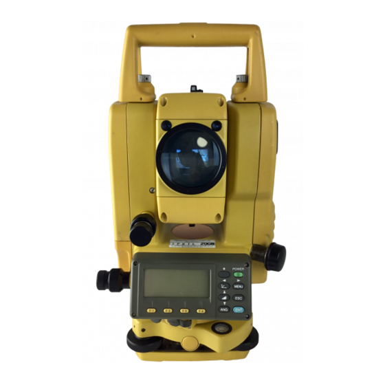
Page 11: Nomenclature And Functions
1 NOMENCLATURE AND FUNCTIONS NOMENCLATURE AND FUNCTIONS 1.1 Nomenclature Handle locking screw Point guide (Point guide type only) Objective lens Instrument center mark Display unit (Only for GTS-233W/235W) Optical plummet telescope Circular level Adjustment screw for circular level Leveling screw Base Tribrach fixing lever... - Page 12 1 NOMENCLATURE AND FUNCTIONS Sighting collimator Battery locking lever Telescope focusing knob Telescope grip On-board battery BT-52QA Telescope eyepiece Instrument center mark *Vertical motion clamp *Vertical tangent screw Horizontal tangent screw Plate level Horizontal Display unit motion clamp Power supply connector Serial Signal connector...
-
Page 13: Display
1 NOMENCLATURE AND FUNCTIONS 1.2 Display ● Display The display uses a dot matrix LCD which has 4 lines and 20 characters per line. In general, the upper three lines display measured data, and the bottom line displays the soft key function which changes with the measuring mode. -
Page 14: Operating Key
1 NOMENCLATURE AND FUNCTIONS 1.3 Operating Key Keys Name of Key Function Star key mode is used for each presetting or displaying as follows. 1 Contrast of the display 2 Reticle illumination 3 Back Light ★ Star key 4 Tilt correction 5 Point guide (Only for point guide model) 6 Set audio mode Coordinate Coordinate measurement mode... -
Page 15: Function Key (Soft Key)
1 NOMENCLATURE AND FUNCTIONS 1.4 Function Key (Soft Key) The Soft Key message is displayed at the bottom line of display. The functions are according to the displayed message. Angle measurement mode Distance measurement mode V: 90°10'20" HR:120°30'40" HR:120°30'40" HD*[r] <<m ↓... -
Page 16: Star Key Mode
1 NOMENCLATURE AND FUNCTIONS Coordinate measurement mode MEAS Start measuring MODE Sets a measuring mode, Fine/Coarse/Tracking Select set audio mode ↓ The function of soft keys is shown on next page (P2). R.HT Sets a prism height by input values. INSHT Sets an instrument height by input values. - Page 17 1 NOMENCLATURE AND FUNCTIONS ● Adjustment the contrast (0 to 9 ) of the display (CONT) This enable you to adjust the contrast of the display. Press the up or down arrow keys to adjust the contrast. ● Adjustment the reticle illumination (1 to 9 ) (RTCL) This enable you to adjust the reticle illumination.
-
Page 18: Serial Signal Rs-232C Connector
1 NOMENCLATURE AND FUNCTIONS 1.6 Serial signal RS-232C connector The serial signal connector is used for connecting the GTS-230W series with a computer or TOPCON Data Collector, which enables the computer to receive measured data from the GTS-230W series or to send preset data of horizontal angle, etc. -
Page 19: Laser Plummet On/Off (Only For Laser Plummet Type)
1 NOMENCLATURE AND FUNCTIONS 1.8 Laser Plummet ON/OFF (Only for Laser Plummet type) Laser plummet option will help you to center the instrument easily onto the measurement point. There are two ways to turn on/off of laser plummet option as follows. ●... -
Page 20: Preparation For Measurement
2 PREPARATION FOR MEASUREMENT PREPARATION FOR MEASUREMENT 2.1 Power Connection (unnecessary if on-board Ni-MH battery BT-52QA is used) See below for connecting the external battery pack. ● Battery pack BT-3Q Power cord , PC-5 is used. ● Large capacity battery pack BT-3L Power cord PC-6 is used. -
Page 21: Setting Instrument Up For Measurement
Mount the instrument to the tripod. Level and center the instrument precisely to insure the best performance. Use tripods with a tripod screw of 5/8 in. diameter and 11 threads per inch, such as the Type E TOPCON wide- frame wooden tripod. Reference: Leveling and Centering the Instrument 1. -
Page 22: Power Switch Key On
2 PREPARATION FOR MEASUREMENT 2.3 Power Switch Key ON Confirm the instrument is leveled. Turn the power switch ON. Power switch key ON TOPCON GTS-230W 90°10'20" 0°00'00" Battery Power Remaining Display ↓ 0SET HOLD HSET ● Confirm the battery power remaining display. Replace with charged battery or charge when battery level is low or indicates “Battery empty”. -
Page 23: Battery Power Remaining Display
2 PREPARATION FOR MEASUREMENT 2.4 Battery Power Remaining Display Battery power remaining display indicates the power condition. 90°10'20" 0°00'00" Measurement is possible. ↓ 0SET HOLD HSET The power is poor. The battery Battery power remaining display should be recharged or replaced. Blinking Measurement is impossible. -
Page 24: Vertical And Horizontal Angle Tilt Correction
2 PREPARATION FOR MEASUREMENT 2.5 Vertical and Horizontal Angle Tilt Correction (GTS-239W has vertical angle tilt correction only.) When the tilt sensors are activated, automatic correction of vertical and horizontal angle for mislevelment is displayed. To ensure a precise angle measurement, tilt sensors must be turned on. The display can also be used to fine level the instrument. - Page 25 2 PREPARATION FOR MEASUREMENT ● Setting Tilt Correction by Soft Key To enable you to select tilt ON/OFF function. setting is not memorized after power is OFF. [Example] Setting X,Y Tilt OFF Operating procedure Option Display Press [F4] key to get the function page 2. 90°10'20"...
-
Page 26: How To Enter Alphanumeric Characters
2 PREPARATION FOR MEASUREMENT 2.6 How to Enter Alphanumeric characters This enables you to enter alphanumeric characters such as the instrument height, prism height, occupied point, backsight point etc.. ● How to select a item [Example setting] Occupied point in the data collection mode. The arrow indicates a item to enter. - Page 27 2 PREPARATION FOR MEASUREMENT Press soft key to select a character. INS.HT: 0.000 m Example: [F4](T) key is pressed. MNOP QRST UVWX [ENT] =TOPCON-1 Select next character in the same manner. INS.HT : 0.000 m MNOP QRST UVWX [ENT] Press [F4](ENT) key.
-
Page 28: Angle Measurement
3 ANGLE MEASUREMENT ANGLE MEASUREMENT 3.1 Measuring Horizontal Angle Right and Vertical Angle Make sure the mode is in Angle measurement. Operating procedure Operation Display Collimate the 1st target (A). Collimate A 90°10'20" HR: 120°30'40" ↓ 0SET HOLD HSET P1 Set horizontal angle of target A at 0°... -
Page 29: Switching Horizontal Angle Right/Left
3 ANGLE MEASUREMENT 3.2 Switching Horizontal Angle Right/Left Make sure the mode is Angle measurement. Operating procedure Operation Display ↓ Press the [F4]( ) key twice to get the function 90°10'20" [F4] on page 3. twice HR: 120°30'40" ↓ 0SET HOLD HSET ↓... -
Page 30: Setting A Horizontal Angle From The Keys
3 ANGLE MEASUREMENT 3.3.2 Setting a Horizontal Angle from the Keys Make sure the mode is Angle measurement. Operating procedure Operation Display Collimate the target. Collimate 90°10'20" HR: 170°30'20" ↓ 0SET HOLD HSET P1 Press the [F3](HSET) key. H ANGLE SET [F3] INPUT --- --- ENTER 1234 5678 90.-[ENT]... -
Page 31: Repetition Angle Measurement
3 ANGLE MEASUREMENT 3.5 Repetition Angle Measurement ● Repetition angle measurement can be done by horizontal angle right measurement mode. Make sure the mode is Horizontal Angle Right measurement. Operating procedure Operation Display ↓ Press the [F4]( ) key to get the function on page 2. [F4] 90°10'20"... -
Page 32: Buzzer Sounding For Horizontal Angle 90° Increments
3 ANGLE MEASUREMENT To return to the normal angle mode, press the [ESC] REPETITION ANGLE [F2](V/H) key or [ESC] key. Exit [F2] > OK? [YES][NO] Press the [F3](YES) key. [F3] 90°10'20" HR: 170°30'20" ↓ 0SET HOLD HSET P1 ● Horizontal angle can be accumulated up to (3600°00'00"... -
Page 33: Compasses ( Vertical Angle)
3 ANGLE MEASUREMENT 3.7 Compasses ( vertical angle) Vertical angle is displayed as shown below. +90° 0° 0° LOCK LOCK -90° Operating procedure Operation Display ↓ Press the [F4]( ) key twice to get the function [F4] 98°10'20" on page 3. twice HR: 170°30'20"... -
Page 34: Distance Measurement
4.2 Setting of the Correction for Prism Constant Topcon’s prism constant value is 0. Set correction for prism at 0. If the prism is of another manufacture, the appropriate constant shall be set beforehand. Refer to Chapter 11 “SETTING THE PRISM CONSTANT VALUE”. -
Page 35: Distance Measurement (N-Time Measurement/Single Measurement)
4 DISTANCE MEASUREMENT 4.4 Distance Measurement (N-time Measurement/Single Measurement) When the number of times measurement is preset, the GTS-230W series measures the distance the set number of times. The average distance will be displayed. When presetting the number of times as 1, it does not display the average distance, because of single measurement. -
Page 36: Fine Mode/Tracking Mode/Coarse Mode
4 DISTANCE MEASUREMENT ● Choose meter /feet / feet+inch unit by soft key It is possible to change the unit for distance measurement mode by soft key. This setting is not memorized after power off. Refer to 16 “SELECTING MODE” to set at the initial setting (memorized after power off). -
Page 37: Stake Out (S.o)
4 DISTANCE MEASUREMENT 4.6 Stake Out (S.O) The difference between the measured distance and the input stake out distance is displayed. Measured distance — Stake out distance = Displayed value ● In stake out operation, you can select either horizontal distance (HD), relative elevation (VD) and slope distance (SD) Operating procedure Operation... -
Page 38: Offset Measurement
4 DISTANCE MEASUREMENT 4.7 Offset Measurement There are four offset measurement modes in the Offset Measurement. ● Angle offset ● Distance offset ● Plane offset ● Column offset To show the offset measurement menu, press the [OFSET] soft key from distance or coordinate measurement mode. -
Page 39: Angle Offset
4 DISTANCE MEASUREMENT 4.7.1 Angle Offset This mode is useful when it is difficult to set up the prism directly, for example at the center of a tree. Place the prism at the same horizontal distance from the instrument as that of point A0 to measure. To measure the coordinates of the center position, operate the offset measurement after setting the instrument height/prism height. - Page 40 4 DISTANCE MEASUREMENT The horizontal distance from the instrument to the OFFSET-MEASUREMENT prism will be measured. 110°20'30" 56.789 m >Measuring... After measuring, the result added offset value will OFFSET-MEASUREMENT be shown. 110°20'30" 56.789 m NEXT Collimate point A using the horizontal motion Collimate OFFSET-MEASUREMENT clamp and horizontal tangent screw.
-
Page 41: Distance Offset Measurement
4 DISTANCE MEASUREMENT 4.7.2 Distance Offset Measurement Measuring distance and coordinate of the center of a pond or a tree of which the radius is known. Measuring the distance or coordinate till P0 point, input oHD value as an offset value and measure P1 point showing as following draw in distance offset measurement. - Page 42 4 DISTANCE MEASUREMENT After measuring, the result added offset value will DISTANCE OFFSET be shown. 80°30'40" 10.000 m NEXT Show the relative elevation of point P0. DISTANCE OFFSET ● Each time pressing the [ ] key, horizontal 80°30'40" distance, relative elevation and slope distance are 11.789 m shown in sequence.
-
Page 43: Plane Offset Measurement
4 DISTANCE MEASUREMENT 4.7.3 Plane Offset Measurement Measuring will be taken for the place where direct measuring can not be done, for example distance or coordinate measuring for a edge of a plane. Three random prism points (P1, P2, P3) on a plane will be measured at first in the plane offset measurement to determine the measured plane. - Page 44 4 DISTANCE MEASUREMENT Collimate PLANE N003#: [F1] MEAS The instrument calculates and displays coordinate 80°30'40" and distance value of cross point between 54.321 m collimation axis and of the plane. *1),2) 10.000 m EXIT Collimate the edge (P0) of the plane. *3) ,4) 75°30'40"...
-
Page 45: Column Offset Measurement
4 DISTANCE MEASUREMENT 4.7.4 Column Offset Measurement If it is possible to measure circumscription point (P1) of column directly, the distance to the center of the column (P0), coordinate and direction angle can be calculated by measured circumscription points (P2) and (P3). - Page 46 4 DISTANCE MEASUREMENT After the measurement, angle measuring display COLUMN OFFSET of the left side (P2) will be shown. Left 120°30'40" Collimate the left side of the column (P2) and Collimate COLUMN OFFSET press the [F4](SET) key. Right After the measurement, angle measuring display [F4] 180°30'40"...
-
Page 47: Coordinate Measurement
5 COORDINATE MEASUREMENT COORDINATE MEASUREMENT 5.1 Setting Coordinate Values of Occupied Point Set the coordinates of the instrument (occupied point) according to coordinate origin, and the instrument automatically converts and displays the unknown point (prism point) coordinates following the origin. It is possible to retain the coordinates of the occupied point after turning the power off. -
Page 48: Setting Height Of The Instrument
5 COORDINATE MEASUREMENT 5.2 Setting Height of the Instrument It is possible to retain the height of instrument after turning the power off. Refer to Chapter 16 “SELECTING MODE”. Operating procedure Operation Display ↓ Press the [F4]( ) key from the coordinate [F4] 123.456 m measurement mode to get the function on page 2. -
Page 49: Execution Of Coordinate Measuring
5 COORDINATE MEASUREMENT 5.4 Execution of Coordinate Measuring Measure the coordinates by entering the instrument height and prism height, coordinates of unknown point will be measured directly. ● When setting coordinate values of occupied point, see Section 5.1 “Setting Coordinate Values of Occupied Point”... -
Page 50: Special Mode (Menu Mode)
6 SPECIAL MODE (Menu Mode) SPECIAL MODE (Menu Mode) By pressing the [MENU] key, the instrument will be in MENU mode. In this mode, special measuring , setting and adjustment are possible. Normal measurement mode [MENU] [ESC] [F1] MENU "DATA COLLECTION MODE" F1:DATA COLLECT See Chapter 7 “DATA COLLECTION”. -
Page 51: Application Measurement (Programs)
6 SPECIAL MODE (Menu Mode) 6.1 Application Measurement (PROGRAMS) 6.1.1 Remote Elevation measurement (REM) To obtain elevation of the point at which setting the target prism is not possible, place the prism at any point on the vertical line from the target then carry out REM procedure as follows. Target K Prism Prism height... - Page 52 6 SPECIAL MODE (Menu Mode) Horizontal distance (HD) between the instrument REM-1 and prism will be shown. <STEP-2> HD* 123.456 m >Measuring... After measuring, the prism position will be REM-1 decided. *2) 1.500 m ––– R.HT HD ––– Collimate target K. Collimate K REM-1 Vertical distance (VD) will be shown.
- Page 53 6 SPECIAL MODE (Menu Mode) After measuring, the prism position will be REM-2 decided. <STEP-2> V : 60°45'50" ––– ––– ––– Collimate ground point G. Collimate G REM-2 <STEP-2> V : 123°45'50" ––– ––– ––– Press the [F4](SET) key. [F4] REM-2 The position of point G will be decided.
-
Page 54: Missing Line Measurement (Mlm)
6 SPECIAL MODE (Menu Mode) 6.1.2 Missing Line Measurement (MLM) Measurement for horizontal distance (dHD), slope distance (dSD), elevation (dVD) and horizontal bearing (HR) between two target prisms. It is possible to enter the coordinate value directly or calculate from coordinate data file. MLM mode has two modes. - Page 55 6 SPECIAL MODE (Menu Mode) Press the [F1] or [F2] key to select using [F2] GRID FACTOR. F1:MLM-1(A-B, A-C) [Example:F2 : DON’T USE] F2:MLM-2(A-B, B-C) Press the [F1] key. MLM-1(A-B, A-C) [F1] <STEP-1> MEAS R.HT ––– Collimate prism A, and press the [F1](MEAS) key. Collimate A MLM-1(A-B, A-C) Horizontal distance (HD) between the instrument...
- Page 56 6 SPECIAL MODE (Menu Mode) ● How to use coordinate data It is possible to input coordinate value directly or calculate from coordinate data file Operating procedure Operation Display To use coordinate data file, select “USE FILE” in step After procedure MLM-1(A-B, A-C) <STEP-1>...
-
Page 57: Setting Z Coordinate Of Occupied Point
6 SPECIAL MODE (Menu Mode) 6.1.3 Setting Z Coordinate of Occupied Point Occupied point coordinate data and known point actual measuring data are utilized, z coordinate of occupied point is calculated and reset again. Known point data and coordinate data can use the coordinate data file. 1) Setting occupied coordinate [Example setting] Using coordinate data file. - Page 58 6 SPECIAL MODE (Menu Mode) 2) Z Coordinate Calculation from Known Point Measuring Data [Example setting] Using coordinate data file Operating procedure Operation Display ↓ After pressing [MENU] key, press [F4](P ) key to [MENU] MENU get the menu on page 2. [F4] F1:PROGRAMS F2:GRID FACTOR...
- Page 59 6 SPECIAL MODE (Menu Mode) HR: 120°30'40" 12.345 m 23.456 m NEXT ––– ––– CALC Press the [F4](CALC) key.*2) Z COORD. SETTING [F4] Z : Z coordinate 1.234 m dZ: Standard deviation dZ : 0.002 m ––– ––– Press the [F4](SET) key. *3) [F4] BACKSIGHT Z coordinate of the occupied point will be set.
-
Page 60: Area Calculation
6 SPECIAL MODE (Menu Mode) 6.1.4 Area Calculation This mode calculate the area of a closed figure. There are two area calculation methods as follows. 1) Area Calculation from Coordinate data file 2) Area Calculation from Measured data ● Area is not calculated correctly if enclosed lines cross each other. ●... - Page 61 6 SPECIAL MODE (Menu Mode) When 3 or more points are set, the area AREA 0021 surrounded by the points is calculated and the 123.456 m.sq result will be shown. NEXT# :DATA-22 LIST UNIT NEXT *1) To set specify point, press the [F1](PT#) key. *2) To show the list of the coordinate data in the file, press the [F2](LIST) key.
- Page 62 6 SPECIAL MODE (Menu Mode) When 3 or more points are measured, the area AREA 0003 surrounded by the points is calculated and the 234.567 m.sq result will be shown. MEAS ––– UNIT ––– *1) Measurement is Fine N-times measurement mode. ●...
-
Page 63: Point To Line Measurement
6 SPECIAL MODE (Menu Mode) 6.1.5 Point to Line Measurement This mode is used to obtain the coordinate data with the origin point A(0,0,0) and the line AB as N axis. Place the 2 prisms at the points A and B on the line, and place the instrument at unknown point C. After measuring the 2 prisms , the coordinate data and the direction angle of the instrument will be calculated and restored. - Page 64 6 SPECIAL MODE (Menu Mode) Collimate prism P1 (Origin) and press [F3](YES) Collimate POINT TO LINE key. MEAS.P1 Measuring starts. *1) [F3] HD*[n] << m >Measuring... Input display of reflector B(P2) height will be REFLECTOR HEIGHT shown. INPUT R.HT: 0.000 m INPUT –––...
-
Page 65: Setting The Grid Factor
6 SPECIAL MODE (Menu Mode) 6.2 Setting the GRID FACTOR GRID FACTOR can reset in this menu mode. For more information, refer to Section 8.1.1”Setting the GRID FACTOR” Operating procedure Operation Display ↓ After pressing the [MENU] key, press the [F4](P [MENU] MENU key to get the menu on page 2. -
Page 66: Setting Illumination Of Display And Cross Hairs
6 SPECIAL MODE (Menu Mode) 6.3 Setting Illumination of Display and Cross Hairs Setting ON/OFF/LEVEL (1 to 9) for illumination of display (LCD) and reticle. ● Setting LEVEL (1 to 9) is only for reticle. [Example setting] LEVEL:2 and turn on the illumination. Operating procedure Operation Display... -
Page 67: Setting Mode 1
6 SPECIAL MODE (Menu Mode) 6.4 Setting Mode 1 In this mode, the following settings are possible. 1. Setting Minimum Reading 2. Auto Power off 3. Vertical and Horizontal Angle Tilt Correction (Tilt ON/OFF) (GTS-239W has vertical angle tilt correction only.). 4. -
Page 68: Auto Power Off
6 SPECIAL MODE (Menu Mode) Press the [F1] key and press the [F4](ENTER) key. [F1] MINIMUM READING [F4] F1:ANGLE F2:COARSE ● To return to previous mode, press the [ESC] key. 6.4.2 Auto Power Off If no key operation is given or no process of measurement is performed for more than 30 minutes ( No change exceeding 30”... -
Page 69: Vertical And Horizontal Angle Tilt Correction ( Tilt On/Off)
6 SPECIAL MODE (Menu Mode) 6.4.3 Vertical and Horizontal Angle Tilt correction ( Tilt ON/OFF) (GTS-239W has vertical angle tilt correction only.) In case the instrument is used in an unstable situation, constant indexing of vertical and horizontal angle may be impossible. In this case, the function of tilt correction can be stopped by selecting TILT OFF. -
Page 70: Selecting Battery Type
6 SPECIAL MODE (Menu Mode) 6.4.5 Selecting Battery Type On-board battery BT-32Q can be also available for GTS-330 series. When you use BT-32Q (Ni-Cd) battery, select [Ni-Cd] type of battery in this parameters 1 menu. If you select wrong type of battery, the battery remaining display may work incorrectly. BT-52QA : Ni-MH battery type, BT-32Q : Ni-Cd battery type. -
Page 71: Selecting Communication Port
6 SPECIAL MODE (Menu Mode) 6.4.7 Selecting Communication Port You can change the communication port to RS-232C port. Operating procedure Operation Display ↓ After pressing the [MENU] key, press the [F4](P [MENU] MENU key twice to get the menu on page 3. [F4] F1:PARAMETERS 1 [F4]... -
Page 72: Confirming The Bluetooth™ Device Address And Setting The Pin Code
6 SPECIAL MODE (Menu Mode) 6.4.8 Confirming the Bluetooth™ Device Address and Setting the PIN code You can confirm the Bluetooth™ address and set the PIN code Operating procedure Operation Display ↓ After pressing the [MENU] key, press the [F4](P [MENU] MENU key twice to get the menu on page 3. -
Page 73: Data Collection
7 DATA COLLECTION DATA COLLECTION The GTS-230W is able to store the measured data into the internal memory. The internal memory is shared by the measured data files and the coordinate data files. Maximum 30 files can be generated. ● Measured data The collected data is memorized into a files. - Page 74 7 DATA COLLECTION ● Data collect menu operation By pressing the [MENU] key, the instrument will be in MENU 1/3 mode. Press the [F1](DATA COLLECT) key, the menu of data collect 1/2 will be shown. Normal measurement mode [ESC] [MENU] MENU F1:DATA COLLECT F2:LAYOUT...
-
Page 75: Preparation
7 DATA COLLECTION 7.1 Preparation 7.1.1 Selecting a File for Data Collection A file used by data collection mode must be selected at first. Select a file before beginning data collection mode because selection screen of a file is displayed. And a selection from data collection menu is possible in the mode. -
Page 76: Selecting A Coordinate File For Data Collection
7 DATA COLLECTION 7.1.2 Selecting a Coordinate File for Data Collection When coordinate data in a coordinate data file are used for occupied point or backsight point, select a coordinate file from the data collect menu 2/2 beforehand. Operating procedure Operation Display DATA COLLECT... - Page 77 7 DATA COLLECTION Enter PT#, press [F4](ENT) key. *1) →PT-11 Enter PT# [F4] INS.HT: 0.000 m INPUT SRCH REC OCNEZ Enter ID, INS.HT in the same way. *2),3) Enter ID, :PT-11 INS.HT INS.HT→ 1.335 m INPUT SRCH REC OCNEZ >REC ? [YES][NO] Press [F3](REC) key.
- Page 78 7 DATA COLLECTION ● Example for setting the direction angle: The following is to memorize the data of the backsight after setting the backsight point from point number. Operating procedure Operation Display → Press the [F2](BACKSIGHT) key from the data [F2] collect menu 1/2.
-
Page 79: Operational Procedure Of "Data Collect
:PT-01 PCODE → R.HT 0.000 m INPUT SRCH MEAS ALL Enter PCODE, R.HT in the same way. *2),3) →PT-01 [F1] Enter PCODE :TOPCON PCODE R.HT 1.200 m [F4] INPUT SRCH MEAS ALL [F1] NEZ OFSET Press the [F3](MEAS) key. EnterR.HT [F4] Collimate the target point. - Page 80 R.HT 1.200 m INPUT SRCH MEAS ALL While executing the DATA COLLECT mode, press [F2] SEARCH [TOPCON] [F2](SRCH) key. *1) F1:FIRST DATA F2:LAST DATA The using file name will appear on the top of the F3:PT# DATA right side of the display.
- Page 81 R.HT 1.200 m and press the [F4](ENT) key. Enter No 1234 5678 90.– [ENT] (Example) [F4] Register number, 32 = TOPCON :PT-02 PCODE :TOPCON → R.HT 1.200 m INPUT SRCH MEAS ALL ● Entering PCODE / ID from the list of PCODE You can also enter PCODE / ID from the list of PCODE.
-
Page 82: Data Collect Offset Measurement Mode
To set this option, refer to Chapter 16 “SELECTING MODE”. Instrument height Occ.Point Operating procedure Operation Display Press the [F3](MEAS) key. →PT-11 [F3] PCODE :TOPCON R.HT 1.200 m INPUT SRCH MEAS ALL NEZ OFSET Press the [F4](OFSET) key. [F4] OFFSET F1:ANG. OFFSET F2:DIST. OFFSET ↓... - Page 83 ] key, N,E and Z –12.345 m coordinate are shown in sequence. >OK? [YES][NO] Press the [F3](YES) key. →PT-12 [F3] PCODE :TOPCON R.HT 1.200 m The data is recorded and the next measuring point INPUT SRCH MEAS ALL is displayed. 7-11...
-
Page 84: Distance Offset Measurement
Left direction offset value.*1) Enter HD INPUT FORWARD HD [F4] oHD: 0.000 m INPUT ––– SKP ENTER Press the [F1](INPUT) key and enter Forward [F1] :PT-11 direction offset value. *1) Enter HD PCODE : TOPCON [F4] R.HT 1.200 m ––– *SD ––– 7-12... - Page 85 N*[n] <<< m Example:[F3](NEZ) key Measuring starts. >measuring ... >Calculating... →PT-12 The data is recorded and the next measuring point is displayed. PCODE :TOPCON R.HT 1.200 m INPUT SRCH MEAS ALL *1) To skip entering, press the [F3](SKP) key. 7-13...
-
Page 86: Plane Offset Measurement
(Prism) (Prism) Prism heights of P1 to P3 is set to zero automatically. Operating procedure Operation Display →PT-11 PCODE :TOPCON R.HT 1.200 m INPUT SRCH MEAS ALL Press the [F3](MEAS) key. [F3] NEZ OFSET Press the [F4](OFSET) key. [F4] OFFSET F1:ANG.OFFSET... - Page 87 [F1] MEAS The display changes to PT# input in the plane PLANE offset measurement. *1) →PT-11 Input point number if necessary. PCODE :TOPCON INPUT SRCH --- MEAS Press the [F4](MEAS) key. [F4] 80°30'40" The instrument calculates and displays coordinate 54.321 m and distance value of cross point between 10.000 m...
-
Page 88: Column Offset Measurement
The direction angle of the center of the column is 1/2 of total direction angle of circumscription points (P2) and (P3). Prism Operating procedure Operation Display →PT-11 PCODE :TOPCON R.HT 1.200 m INPUT SRCH MEAS ALL Press the [F3](MEAS) key. [F3] NEZ OFSET Press the [F4](OFSET) key. -
Page 89: Nez Auto Calculation
→PT-12 Press the [F3](YES) key. The display returns to the [F3] next point number in data collect mode. PCODE :TOPCON R.HT 1.200 m INPUT SRCH MEAS ALL 7.4 NEZ Auto Calculation As measured data is collected, coordinates are calculated and stored for traverse or topo collection. -
Page 90: Editing Pcode Library [Pcode Input]
Display DATA COLLECT F1:SELECT A FILE F2:PCODE INPUT ↓ F3:CONFIG. Press the [F2](PCODE INPUT) key from Data [F2] Collect menu 2/2. →001:TOPCON 002:TOKYO EDIT ––– ––– By pressing the following keys, the list will increase 011:URAH ]or[ or decrease. →012:AMIDAT... -
Page 91: Setting Parameter Of Data Collect [Config.]
7 DATA COLLECTION 7.6 Setting Parameter of Data Collect [CONFIG.] In this mode, the following settings of data collect mode are possible. ● Setting Items Menu Selecting Item Contents Select Fine /Coarse(1) /Coarse(10) mode in distance measurement mode. The unit to be displayed is as follows. FINE / CRS(1) / F1:DIST MODE CRS(10) -
Page 92: Layout
8 LAYOUT LAYOUT LAYOUT mode has two functions which are setting of layout points and setting new points using coordinate data in the internal memory. Also, if the coordinate data is not stored in the internal memory, this can be input from key board. The coordinate data is loaded from PC to the internal memory via RS-232C. - Page 93 8 LAYOUT ● Layout menu operation By pressing the [MENU] key, the instrument will be in MENU 1/3 mode. Press the [F2](LAYOUT) key, the menu of layout 1/2 will be shown. Normal measurement mode [ESC] [MENU] MENU F1:DATA COLLECT F2:LAYOUT ↓...
-
Page 94: Preparation
8 LAYOUT 8.1 Preparation 8.1.1 Setting the GRID FACTOR ● Calculation Formula 1) Elevation Factor : The average radius of the earth Elevation Factor = R+ELEV. ELEV. : The elevation above mean sea level 2) Scale Factor Scale Factor : Scale Factor at the surveying station 3) Grid Factor Grid Factor = Elevation Factor ×... -
Page 95: Selecting Coordinate Data File
8 LAYOUT 8.1.2 Selecting Coordinate Data File You can execute a Layout from selected coordinate data file, also you can record New point measured data into the selected coordinate data file. ● The only coordinate data file existing can be selected and you can not make a new file in this mode. For more information about File, refer to Chapter 9 “MEMORY MANAGER MODE”. -
Page 96: Setting Occupied Point
8 LAYOUT 8.1.3 Setting Occupied Point Occupied point can be set by two setting methods as follows. 1) Setting from the coordinate data stored in the internal memory. 2) Direct key input of coordinate data. ● Example setting :Setting the occupied point from the internal coordinate data file Operating procedure Operation Display... -
Page 97: Setting Backsight Point
8 LAYOUT 8.1.4 Setting Backsight Point The following three setting methods for Backsight point can be selected. 1) Setting from the coordinate data file stored in the internal memory. 2) Direct key input of coordinate data. 3) Direct key input of setting angle. ●... - Page 98 8 LAYOUT ● Example setting: Setting the backsight point coordinates directly Operating procedure Operation Display Press the [F2](BACKSIGHT) key from the Layout [F2] BACKSIGHT menu 1/2. PT#: INPUT LIST NE/AZ ENT Press the [F3] (NE/AZ) key. [F3] N→ 0.000 m 0.000 m INPUT –––...
-
Page 99: Executing A Layout
8 LAYOUT 8.2 Executing a Layout The following methods can be selected for executing a Layout: 1) Recalling points from internal memory by point number. 2) Direct key input of coordinate values. Example setting : Recalling point from internal memory. Operating procedure Operation Display... - Page 100 8 LAYOUT When the display value dHR, dHD and dZ are equal to 0, the layout point is established.*3 Press the [F3](NEZ) key. [F3] 100.000 m The coordinate data is shown. 100.000 m 1.015 m MODE ANGLE ––– NEXT Press the [F4](NEXT) key to set next layout point . LAYOUT [F4] PT# is automatically incremented.
-
Page 101: Setting A New Point
8 LAYOUT 8.3 Setting a New Point New point is required for example when a layout point cannot be sighted from existing control points. 8.3.1 Side Shot Method Set up the instrument at a known point, and measure the coordinate of the new points by the side shot method Known Point B New Point... - Page 102 8 LAYOUT Press the [F4](ENTER) key. [F4] SIDE SHOT The file will be set . PT#: INPUT SRCH ––– ENTER Press the [F1](INPUT) key, and enter the new [F1] REFLECTOR HEIGHT point name. *4) Enter PT# INPUT Press the [F4](ENT) key. [F4] R.HT 0.000 m...
-
Page 103: Resection Method
8 LAYOUT 8.3.2 Resection Method Set up the instrument at a new point, and calculate the coordinate of the new point using the coordinate data of maximum seven known points and the measurements made to these points. By following observation, resection is possible. •... - Page 104 8 LAYOUT Enter instrument height in the same way. [F1] NO01# Enter PT#: INS.HT [F4] INPUT LIST NEZ ENTER Enter the known point A number. *3) [F1] REFLECTOR HEIGHT Enter PT# INPUT [F4] R.HT 0.000 m INPUT ––– ––– ENTER Enter reflector height.
- Page 105 8 LAYOUT Press the [F4](CALC) key. *6) [F4] Standard Deviation Standard Deviation will be shown. 1.23 sec. Unit : (sec.) or (mGON) or (mMIL) ↓ ––– ––– ↓ Press the [F2]( ) key. SD(n) : 1.23 mm [F2] Standard Deviations of each coordinate will be SD(e) : 1.23 mm shown.
- Page 106 [Example: Executing Layout Mode] Operating procedure Operation Display LAYOUT PT#: INPUT LIST NEZ ENTER While executing the LAYOUT mode, press the [F2] [TOPCON [F2](LIST) key. →DATA-01 → The arrow( ) indicates selected data. DATA-02 VIEW SRCH ––– ENTER By pressing the following keys, the list will increase...
-
Page 107: Memory Manager Mode
9 MEMORY MANAGER MODE MEMORY MANAGER MODE The following items for internal memory are available in this mode. 1) FILE STATUS Checking the number of stored data / Remaining internal memory capacity. 2) SEARCH Searching the recorded data. 3) FILE MAINTAN. Deleting files / Editing file name 4) COORD. -
Page 108: Display Internal Memory Status
9 MEMORY MANAGER MODE 9.1 Display Internal Memory Status This mode is used to check the internal memory status. Operating procedure Operation Display Press the [F3](MEMORY MGR. ) key from the MEMORY MGR. [F3] menu 1/3. F1:FILE STATUS F2:SEARCH ↓ F3:FILE MAINTAN P Press the [F1](FILE STATUS) key. -
Page 109: Searching Data
9 MEMORY MANAGER MODE 9.2 Searching Data This mode is used to search the recorded file data in the DATA COLLECT or LAYOUT mode. The following 3 search methods in each type of files can be selected. First data search Last data search Point number search(MEAS.DATA, COORD.DATA) Number search (PCODE LIB.) - Page 110 9 MEMORY MANAGER MODE ● To edit the data in searching mode Point name (PT#, BS#) , ID, PCODE and Height data (INS.HT, R.HT) can be corrected in the searching mode. Measured value can not be corrected. Operating procedure Operation Display ...
-
Page 111: Coordinate Data Searching
9 MEMORY MANAGER MODE 9.2.2 Coordinate Data Searching Example searching :Point number searching Operating procedure Operation Display Press the [F3](MEMORY MGR.) key from the [F3] MEMORY MGR. menu 1/3. F1:FILE STATUS F2:SEARCH ↓ F3:FILE MAINTAN Press the [F2](SEARCH) key. SEARCH [F2] F1:MEAS. -
Page 112: Pcode Library Searching
9 MEMORY MANAGER MODE 9.2.3 PCODE LIBRARY Searching Example searching :Number searching Operating procedure Operation Display Press the [F3](MEMORY MGR.) key from the [F3] MEMORY MGR. menu 1/3. F1:FILE STATUS F2:SEARCH ↓ F3:FILE MAINTAN Press the [F2](SEARCH) key. SEARCH [F2] F1:MEAS. -
Page 113: File Maintenance
9 MEMORY MANAGER MODE 9.3 FILE MAINTENANCE In this mode, the following items are available. Renaming file name / Searching data in a file / Deleting files ● FILE MAINTAN. menu MEMORY MGR. F1:FILE STATUS F2:SEARCH ↓ F3:FILE MAINTAN. P [ESC] [F3] @AMIDAT... -
Page 114: Rename A File
9 MEMORY MANAGER MODE 9.3.1 Rename a File An existing file in internal memory can be renamed. Operating procedure Operation Display Press the [F3](FILE MAINTAN.) key from the [F3] Memory manager menu 1/3. →MEASD1 /M0123 COORD1 /C0056 SRCH ––– Select a file by pressing r[] key. -
Page 115: Deleting A File
9 MEMORY MANAGER MODE 9.3.3 Deleting a File This mode erases a file from internal memory. Only one file can be erased at a time. Operating procedure Operation Display Press the [F3](FILE MAINTAN.) key from the [F3] Memory manager menu 1/3. →MEASD1 /M0123 COORD1... -
Page 116: Coordinate Data Direct Key Input
––– ENTER Enter coordinate data in the same way. [F1] COORD. DATA INPUT Enter COORD. PT#:TOPCON-102 Next input display is shown, point number (PT#) is [F4] automatically incremented. INPUT LIST ––– ENTER *1) Refer to Section 2.6 “How to Enter Alphanumeric characters”. -
Page 117: Delete A Coordinate Data From A File
9 MEMORY MANAGER MODE 9.5 Delete a Coordinate Data from a File Coordinate data in a file can be erased. Operating procedure Operation Display Press the [F3](MEMORY MGR.) key from the MEMORY MGR. [F3] menu 1/3. F1:FILE STATUS F2:SEARCH ↓ F3:FILE MAINTAN ↓... -
Page 118: Editing Pcode Library
Press the [F4](P ) key. [F4] MEMORY MGR. F1:COORD. INPUT F2:DELETE COORD. ↓ F3:PCODE INPUT Press the [F3](PCODE INPUT) key. [F3] →001:TOPCON 002:TOKYO EDIT ––– ––– By pressing the following keys, the list will increase 011:URAH ]or[ or decrease. →012:AMIDAT ]or[... -
Page 119: Data Communications
9 MEMORY MANAGER MODE 9.7 Data Communications You can send a data file stored in the internal memory to a computer directly. Also, you can directly load a coordinate data file and PCODE Library data to the internal memory from the computer. 9.7.1 Sending Data Example: Sending a Measured data file Operating procedure... -
Page 120: Loading Data
9 MEMORY MANAGER MODE 9.7.2 Loading Data Coordinate data files and PCODE Library data can be loaded from PC. Example: Loading a coordinate data file Operating procedure Operation Display Press the [F3](MEMORY MGR.) key from the [F3] MEMORY MGR. menu 1/3. F1:FILE STATUS F2:SEARCH ↓... -
Page 121: Setting Parameter Of Data Communications
9 MEMORY MANAGER MODE 9.7.3 Setting Parameter of Data Communications ● Items of the Parameter Item Selecting Item Contents Setting Protocol [ACK/NAK], F1: Protocol [ONE WAY] [ACK/NAK] or [ONE WAY] communication Setting transfer speed 1200, 2400, 4800, F2: Baud rate 9600, 19200,38400 1200/2400/4800/9600 /19200/ 38400 baud rate Setting data length and parity. -
Page 122: Confirming The Parameters For Bluetooth™ Communication
9 MEMORY MANAGER MODE 9.7.4 Confirming the parameters for Bluetooth™ communication The communication parameters for the Bluetooth™ are fixed as follows. You can only confirm the parameters in Memory manager mode. ● Fixed parameters for Bluetooth™ communication Item Fixed parameters Baud rate 38400 baud rate Char. -
Page 123: Set Audio Mode
10 SET AUDIO MODE SET AUDIO MODE The light acceptance quantity level for the EDM (SIGNAL), the atmospheric correction value (PPM) and correction value of prism constant (PSM) are displayed in this mode. When reflected light from the prism is received a buzzer sounds. This function is good for easy collimation when the target is difficult to find. -
Page 124: Setting The Prism Constant Value
11 SETTING THE PRISM CONSTANT VALUE SETTING THE PRISM CONSTANT VALUE The prism constant value of Topcon is set to zero. When using prisms other than Topcon’s, it is necessary to set the prism constant correction value of that specific prism. -
Page 125: Setting Atmospheric Correction
12 SETTING ATMOSPHERIC CORRECTION SETTING ATMOSPHERIC CORRECTION The velocity of light through air is not constant and depends on the atmospheric temperature and pressure. The atmospheric correction system of this instrument corrects automatically when the correction value is set. 15°C/59°F, and 1013.25hPa / 760mmHg / 29.9 inHg is as a standard value for 0ppm in this instrument. - Page 126 12 SETTING ATMOSPHERIC CORRECTION ● How to Set the Atmospheric Correction Value Directly Measure the temperature and air pressure to find atmospheric correction value (PPM) from the chart or correction formula. Operating procedure Operation Display Press the [F3](S/A) key to set Set Audio Mode [F3] SET AUDIO MODE from distance or coordinate measurement mode.
- Page 127 12 SETTING ATMOSPHERIC CORRECTION Atmospheric Correction Chart (For your reference) The atmospheric correction value is obtained easily with the atmospheric correction chart. Find the measured temperature in horizontal, and pressure in vertical on the chart. Read the value from the diagonal line, which represents the required atmospheric correction value. Example: The measured temperature is +26°C The measured pressure is 1013 hPa...
- Page 128 12 SETTING ATMOSPHERIC CORRECTION 12-4...
- Page 129 12 SETTING ATMOSPHERIC CORRECTION 12-5...
-
Page 130: Correction For Refraction And Earth Curvature
13 CORRECTION FOR REFRACTION AND EARTH CURVATURE CORRECTION FOR REFRACTION AND EARTH CURVATURE The instrument measures distance, taking into account correction for refraction and earth curvature. 13.1 Distance Calculation Formula Distance Calculation Formula; with correction for refraction and earth curvature taken into account. Follow the Formula below for converting horizontal and vertical distances. -
Page 131: Power Source And Charging
14 POWER SOURCE AND CHARGING POWER SOURCE AND CHARGING 14.1 On-board Battery BT-52QA ● To remove Confirm that the instrument is turned off before removing the battery. Push the battery locking lever and pull out the BT-52QA on-board battery as shown below. ●... - Page 132 14 POWER SOURCE AND CHARGING ● To install Place the base of the on-board battery into the GTS-230W series, push the on-board battery toward the instrument side till the battery clicks into position. ● Do not charge or discharge continuously, otherwise the battery and the charger may be deteriorated.
-
Page 133: Detach/Attach Of Tribrach
15 DETACH/ATTACH OF TRIBRACH DETACH/ATTACH OF TRIBRACH The instrument is easily detached or attached to the tribrach, with a tribrach locking lever loosened or tightened for this purpose. ● Detachment 1) Loosen the tribrach locking lever, by revolving it 180° or 200g in the counterclockwise direction (which will point the triangle mark upwards). -
Page 134: Selecting Mode
16 SELECTING MODE SELECTING MODE 16.1 Items of the Selecting Mode The following modes are available. Menu Items Selecting item Display TEMP. & °C / °F Select the unit of temperature for atmospheric UNIT SET PRES. hPa / mmHg / correction. - Page 135 16 SELECTING MODE EDM OFF 0-99 The time when EDM is cut off from distance TIME measurement is completed can be changed. This function is effective for shortening the first time measuring time when distance measurement is started from distance measurement completing state.
-
Page 136: How To Set Selecting Mode
16 SELECTING MODE ACK MODE STANDARD / Set the procedure of the communication with OMITTED external device. STANDARD:Normal procedure OMITTED:Even though the [ACK] is omitted from the external device, the data is not sent again. GRID USE G.F. / Select using GRID FACTOR in calculation of FACTOR DON’T USE measurement data. - Page 137 16 SELECTING MODE Press [F3](OTHERS SET) key. [F3] OTHERS SET F1:H-ANGLE BUZZER F2:S/A BUZZER ↓ F3:W-CORRECTION ↓ Press [F4](P ) key, to get the function in page 2 . OTHERS SET [F4] F1:NEZ MEMORY F2:REC TYPE F3:CR,LF ↓ Press [F1] key. [F1] NEZ MEMORY [OFF]...
-
Page 138: Check And Adjustment
5) If using above procedure and no difference is found from the instrument constant at the factory or a difference of over 5mm is found, contact TOPCON or your TOPCON dealer. Note: The seal with which the value is written is stuck on the lower part of the instrument, or the battery removal side of the instrument. -
Page 139: Checking The Optical Axis
Note: If displacement is more than one-fifth in the above case, and still remains so after rechecking the original line of sight, the instrument must be adjusted by competent technicians. Please contact TOPCON or your TOPCON dealer to adjust the instrument. Red light spot... -
Page 140: Checking/Adjusting The Theodolite Functions
17 CHECK AND ADJUSTMENT 17.3 Checking/Adjusting the Theodolite Functions ● Pointers on the Adjustment 1) Adjust the eyepiece of the telescope properly prior to any checking operation which involves sighting through the telescope. Remember to focus properly, with parallax completely eliminated. 2) Carry out the adjustments in the order of item numbers, as the adjustments are dependent one upon another. -
Page 141: Checking /Adjusting The Plate Level
17 CHECK AND ADJUSTMENT 17.3.1 Checking /Adjusting the Plate Level Adjustment is required if the axis of the plate level is not perpendicular to the vertical axis. ● Check 1) Place the plate level parallel to a line running through the centers of two leveling screws, say, A and B. -
Page 142: Adjustment Of The Vertical Cross-Hair
17 CHECK AND ADJUSTMENT 17.3.3Adjustment of the Vertical Cross-hair Adjustment is required if the vertical cross-hair is not in a place perpendicular to the horizontal axis of the telescope ( since it must be possible to use any point on the hair for measuring horizontal angles or running lines). -
Page 143: Collimation Of The Instrument
17 CHECK AND ADJUSTMENT 17.3.4 Collimation of the Instrument Collimation is required to make the line of sight of the telescope perpendicular to the horizontal axis of the instrument, otherwise, it will not be possible to extend a straight line by direct means. ●... -
Page 144: Checking / Adjusting The Optical Plummet Telescope
17 CHECK AND ADJUSTMENT Note: 1 First, loosen the capstan adjustment screw on the side to which the vertical cross-hair line must be moved. Then tighten the adjustment screw on the opposite side by an equal amount which will leave the tension of the adjustment screws unchanged. Revolve in the counterclockwise direction to loosen and in the clockwise direction to tighten, but revolve as little as possible. -
Page 145: Checking / Adjusting The Laser Plummet (For Laser Plummet Type)
17 CHECK AND ADJUSTMENT 17.3.6 Checking / Adjusting the Laser Plummet (For Laser Plummet type) ● Check 1) Turn on the laser plummet and coincide the center of the laser with a measuring point. 2) Rotate the instrument 180° or 200g around the vertical axis and check the measuring point. If the laser is properly centered in the measuring point, adjustment is not required. -
Page 146: Adjustment Of Vertical Angle 0 Datum
17 CHECK AND ADJUSTMENT 17.3.7Adjustment of Vertical Angle 0 Datum If when measuring the vertical angle of target A at telescope position normal (direct) and reverse settings, the amount of normal and reverse measurements combined is other than 360° (ZENITH-0), half of the difference from 360°... -
Page 147: How To Set The Instrument Constant Value
17 CHECK AND ADJUSTMENT 17.4 How to Set the Instrument Constant Value To set the Instrument constant which is obtained in Section 17.1 “Check and adjusting of instrument constant”, follow as below. Operating procedure Operation Display While pressing the [F1] key, turn power switch [F1] ADJUSTMENT MODE F1:V ANGLE 0 POINT... -
Page 148: Adjustment Of Compensation Systematic Error Of Instrument
17 CHECK AND ADJUSTMENT 17.5 Adjustment of Compensation Systematic Error of Instrument (Only for GTS-233W/235W/236W) Operating procedure Operation Display Level the instrument properly with the ADJUSTMENT MODE [F1] plate level. F1:V ANGLE 0 POINT Power ON F2:INST. CONSTANT While pressing the [F1] key, turn power switch ON. ↓... - Page 149 17 CHECK AND ADJUSTMENT Press the [F4](SET) key. Repeat the procedures in step so that the count of measured COMPLETE times matches to the one in FACE(2). Then the display returns to main menu. ● To show the constant list of systematic error of ADJUSTMENT MODE instrument F1:V ANGLE 0 POINT...
-
Page 150: Reference Frequency Check Mode
17 CHECK AND ADJUSTMENT 17.6 Reference frequency check mode The beam modulated by the reference frequency of EDM is emitted continuously. This mode is used for frequency test mainly. Operating procedure Operation Display While pressing the [F1] key, turn power switch [F1] ADJUSTMENT MODE F1:V ANGLE 0 POINT... -
Page 151: Precautions
12) Even if any abnormality occurs, never attempt to disassemble or lubricate the instrument yourself. Always consult with TOPCON or your dealer. 13) To remove the dust on the case, never use thinner or benzine. Use a clean cloth moistened with neutral detergent. -
Page 152: Special Accessories
● Occupied point, coordinate data and other data can ● Capacity: 6AH be input from DK-7W. It is also possible to control ● External dimensions: GTS-230W series from DK-7W. 190(L) × 106(W) × 74(H) mm ● Weight:2.8kg Interface cable F-24 Interface cable P-14 ●... - Page 153 19 SPECIAL ACCESSORIES Power cord PC-6 (For BT-3L) Power cord PC-3 (For AC-5) ● L-shape plug provided ● L-shape plug provided ● Cord length: 2m approx. ● Cord length: 2m approx. Solar reticle, Model 6 Trough compass, Model 6 ● A reticle designed for collimation of the sun. ●...
- Page 154 19 SPECIAL ACCESSORIES Gadget case, Model 1 Back pack, Model 2 ● Convenient for use in mountainous terrain. A case to store and carry accessories. ● External dimensions: 300(L)×145(W)×220(H) mm ● Weight:1.4kg Prism unit case, Model 6 Prism unit case, Model 3 Fixed 9 prisms unit or tilting 3 prisms unit can be This is the plastic case to store and carry various sets stored in this case.
-
Page 155: Battery System
In case of On-board battery In case of External battery Pack BT-52QA BT-3L PC-6 PC-3 PC-5 Car battery PC-6 AC-5 GTS-230W series GTS-230W series Charging Charging time Quick BC-27BR/CR BC-27BR for AC 120V use BC-27CR for AC 230V use Approx. 1.8h BT-52QA... -
Page 156: Prism System
21 PRISM SYSTEM PRISM SYSTEM Arrangement according to your needs is possible. Target pole-2 (not used with 9 prisms) Prism-2 Tilting prism Tilting prism Single prism Triple prism Tilting triple prism holder-1 9 prism holder-2 holder-3 holder-2 holder-2 holder-2 with target plate-2 Tribrach Tribrach... -
Page 157: Error Displays
Level the instrument then carry the angle 0-position is adjusted. adjustment work. Mainly at the time data transmission Confirm operation procedure is correct or the E80’s between GTS-230W series and external connection cables are correct. instrument. Abnormality in internal memory Repair is required. E90’s system. - Page 158 If this error code continues to display, repair is H ANGLE Abnormality in angle measuring system. ERROR required. VH ANGLE ERROR ● If error still persist after attempting to clear them, contact your local Topcon dealer or Topcon head office. 22-2...
-
Page 159: Specifications
23 SPECIFICATIONS SPECIFICATIONS Telescope Length : 150mm Objective lens : 45mm (EDM 50mm) Magnification : 30× Image : Erect Field of view : 1°30' Resolving power : 2.5" Minimum focus : 1.3m Reticle illumination : Provided Distance measurement Measurement range Atmospheric conditions Model Prism... - Page 160 23 SPECIFICATIONS Electronic Angle Measurement Method : Absolute reading Detecting system: Horizontal angle GTS-233W/235W : 2 sides GTS-236W/239W : 1 side Vertical angle : 1 side Minimum reading GTS-233W/235W/236W : 5" / 1" (1mgon / 0.2mgon) reading GTS-239W : 10" / 5" (2mgon / 1mgon) reading Accuracy(Standard deviation based on DIN 18723 ) GTS-233W : 3"(1mgon )
- Page 161 23 SPECIFICATIONS Laser Plummet (only for Laser plummet type) Light source : L.D (Visible laser) Wave length : 633nm Out put : 1mW maximum Laser class : CLASS 2 (ll) laser product Dimension : 336(H)×184(W)×174(L) mm (13.2(H)×7.2(W)×6.9(L) in) Weight Instrument (with battery) : 4.9kg ( 10.8 lbs) (without battery)
-
Page 162: Appendix
APPENDIX APPENDIX Dual Axis Compensation Inclination of the vertical axis with respect to true vertical will result in incorrectly measured horizontal angles. The extent of the error in horizontal angle measurement due to axis tilt depends on three factors : ●... - Page 163 APPENDIX It is clear from the table that dual axis compensation has the most benefit when the elevation of the target is greater then 30° and the axis is tilted more than 10". The entries indicated in bold in the table show, in fact, that for many common surveying applications i.e. target elevation <30°...
-
Page 164: Precaution When Charging Or Storing Batteries
APPENDIX Precaution when Charging or Storing Batteries The capacity of battery will be affected and its service life shortened in any of the following cases while it is recharged, dischrged or stored. 1) Recharging Fig. 1 shows how ambient temperature at recharging is related to charging efficiency or as affecting discharge capacity. - Page 165 APPENDIX 0.1C charge Discharge : 0.2, E.V.= Temperature at discharge : 20 Ambient temperature when charging i Fig.1 Recharging 0.2C discharge 1C discharge Charging : 0.1C ~16hours Charging temperature : 20 Ambient temperature i Fig. 2 Discharge Charging : 0.1C ~16hours Discharge : 0.2 C, E.V.=1.0V Storing period (month)
- Page 166 ™ ™ ™ Bluetooth and the Bluetooth logos are trademarks owned by Bluetooth SIG, Inc., USA and licensed to Topcon Corporation.
- Page 167 TOPCON (GREATBRITAIN) LTD. TOPCON POSITIONING SYSTEMS, INC. HEAD OFFICE 5758 West Las Positas Blvd., Pleasanton, CA 94588, U.S.A. Topcon House Kennet Side, Bone Lane, Newbury, Berkshire RG14 5PX U.K. Phone: 925-460-1300 Fax: 925-460-1315 www.topcon.com Phone: 44-1635-551120 Fax: 44-1635-551170 TOPCON CALIFORNIA survey.sales@topcon.co.uk laser.sales@topcon.co.uk...
Need help?
Do you have a question about the GTS-235W and is the answer not in the manual?
Questions and answers