Advertisement
Quick Links
NEBMM23G15EH...Q7...R3LEG14
Motor cable
Instructions | Assembly
8089487
2018-06
[8089489]
Translation of the original instructions
1
Further applicable documents
All available documents for the product è www.festo.com/pk.
Observe further applicable documents:
–
Instruction manual for the servo drive CMMT-AS
–
Instruction manual for the accessories for servo drive CMMT-AS
2
Safety
2.1
Safety instructions
–
Do not connect or disconnect plug connector when powered.
–
Only assemble the product on components that are in a condition to be safely
operated.
2.2
Intended use
Connection of the motor and encoder of the motor EMMT-AS to the servo drive
CMMT-AS.
3
Configuration
3.1
Product design
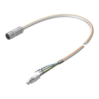
Fig. 1
3.2
Contact assignment
Field device side
Pin
Insu
lated
wire
Socket M23x1
A
BU
B
BN
C
BK
D
–
PE
GNYE
1
BUWH
2
–
3
–
4
GNWH
5
BNGN
6
WH
7
GY
8
PK
9
VT
10
YE
1) Colour code in accordance with IEC 60757:1983-01
Tab. 1 Contact assignment
4
Mounting
4.1
Assembly, field device side
1. Align socket 1 to match plug. Note arrow marking.
Festo AG & Co. KG
Ruiter Straße 82
73734 Esslingen
Germany
+49 711 347-0
www.festo.com
1 Socket M23x1, 15-pin
2 Plug connector RJ45
3 Cable end sleeve (6x)
4 Cable
5 Screened connection
Controller side
Function/signal
1)
Wire ends -
U
Motor power supply
LE
V
W
–
PE
BR–
Brake (optional)
–
Not assigned
–
BR+
Brake (optional)
Pin, plug
7
Up
RJ45
8
OV
4
DATA+
5
DATA–
1
CLK+
2
CLK-
2. Connect socket 1 to the plug.
3. Tighten the screw-type lock of the socket 1. Tightening torque:
1.2 Nm ± 10 %
NOTICE!
Movements of the cable can cause malfunction and material damage.
Push-in connector on the field device is damaged by transferred application of
force.
•
Ensure sufficient strain relief at a maximum 30 cm away from the socket.
4.2
Assembly, controller side
1. Connect the wires in accordance with the contact assignment.
2. Connect the plug 2 to the matching socket and click into place.
3. Relieve strain on motor cable è 1 Further applicable documents.
4.3
Installation
Mounting in energy chain
1. Lay the chain out lengthwise.
2. Place the cables in the chain, making sure they are not twisted.
8089487
3. Separate cables from each other using separators/drill holes.
4. Do not connect cables together.
Fig. 2
5. Maintain space X. X > 10 % of the cable diameter D.
If the chain is suspended vertically, increase the space X.
Fig. 3
6. Align chain in the operating position:
–
Make sure that the radius is greater than the bending radius R of the
cables.
–
Cables can move freely in the bending radius KR of the energy chain.
Ä Cables are not forced through the chain.
7. Mount chain (è corresponding instructions).
8. Fasten cables:
–
At both ends of the chain in case of short energy chains
–
Only at the driver end in the case of long, sliding energy chains
Fig. 4
9. Do not bend cables all the way to the fastening point.
Ä Mounting space A between the fastening point and bending movement is
observed.
NOTICE!
Damage to cables if the chain breaks.
•
Replace cables after a chain break.
NOTICE!
Malfunction and material damage due to vertically suspended cables.
The cables stretch.
•
Regularly check the length of the cables.
•
Readjust the cables if required.
Advertisement

Subscribe to Our Youtube Channel
Related Manuals for Festo NEBM-M23G15-EH-...-Q7...-R3LEG14 Series


Summary of Contents for Festo NEBM-M23G15-EH-...-Q7...-R3LEG14 Series
- Page 1 3. Separate cables from each other using separators/drill holes. 4. Do not connect cables together. Translation of the original instructions Further applicable documents All available documents for the product è www.festo.com/pk. Observe further applicable documents: – Instruction manual for the servo drive CMMT-AS –...
- Page 2 [mm] Current rating at 40 °C 11.7 Surge resistance [kV] CE marking (see declaration of In accordance with Low Voltage Directive conformity): è www.festo.com/sp Operating voltage range 0 … 630 0 … 850 Degree of protection Degree of protection IP67 Note on degree of protection In assembled state...
Need help?
Do you have a question about the NEBM-M23G15-EH-...-Q7...-R3LEG14 Series and is the answer not in the manual?
Questions and answers