Table of Contents
Advertisement
Quick Links
B-Tronic VarioControl
VC4200B
Assembly and Operating Instructions
en
Flush-mounted radio receiver
Important information for:
• Fitters / • Electricians / • Users
Please forward accordingly!
These instructions must be kept safe for future reference.
4035 630 040 0d 13/02/2018
Becker-Antriebe GmbH
Friedrich-Ebert-Straße 2-4
35764 Sinn/Germany
www.becker-antriebe.com
Advertisement
Table of Contents

Related Manuals for Becker B-Tronic VarioControl VC4200B


Summary of Contents for Becker B-Tronic VarioControl VC4200B
- Page 1 Assembly and Operating Instructions Flush-mounted radio receiver Important information for: • Fitters / • Electricians / • Users Please forward accordingly! These instructions must be kept safe for future reference. 4035 630 040 0d 13/02/2018 Becker-Antriebe GmbH Friedrich-Ebert-Straße 2-4 35764 Sinn/Germany www.becker-antriebe.com...
-
Page 2: Table Of Contents
Table of contents General .................... 3 Warranty .................... 3 Safety instructions ................... 4 Intended use ................... 5 Explanation of displays and buttons ............ 6 Wiring ..................... 9 Programming transmitters ............... 12 Limit position adjustment and configurations.......... 13 Deleting transmitters................ 14 Restoring to factory settings .............. 14 Technical data for the flush-mounted radio receiver........ 15 What to do if...?.................. 16 Simplified EU declaration of conformity............. 17... -
Page 3: General
General The flush-mounted radio receiver, delivered ex works, converts radio signals into control signals. A wired drive can be radio-controlled using the radio re- ceiver. The radio receiver can be operated by all the transmitters in the B- Tronic range of control units. Please observe these Assembly and Operating Instructions when installing and setting up the equipment. -
Page 4: Safety Instructions
Safety instructions The following safety instructions and warnings are intended to avert hazards and to prevent property damage and personal injury. General information • Always comply with regulations of local energy supply companies as well as VDE 100 provisions for wet and damp rooms during installation. •... -
Page 5: Intended Use
Intended use The radio receiver described by the present instructions must only be used for the operation of roller shutter, blind and ON/OFF control units (e.g. lighting equipment). • Please note that radio-controlled systems may not be used in areas with a high risk of interference (e.g. -
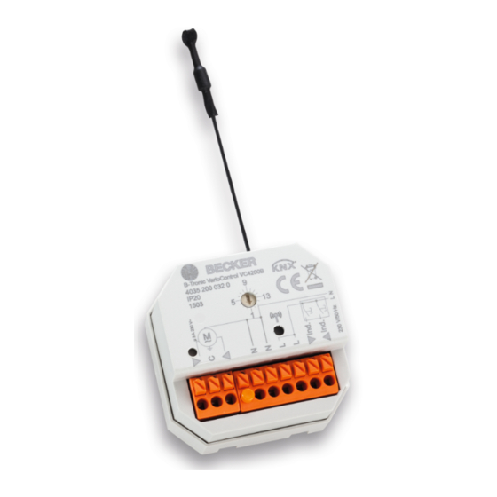
Page 6: Explanation Of Displays And Buttons
Explanation of displays and buttons B-Tronic VarioControl VC4200B 4035 200 032 0 110-240V/50-60Hz 0,7W IP20 1627... - Page 7 1. Antenna 2. Function selection switch Position 0 Reference (LED briefly lights up red) (Positions 0-15) Position 1 Roller shutter (current detection active) Position 2 Venetian blind (current detection active) Position 3 ON/OFF Position 4 ON and OFF after 10 minutes Position 5 ON and OFF after 3...
- Page 8 Extra functions Roller shutter Venetian blind ON/OFF ON and OFF after 10 minutes ON and OFF after 3 minutes Pulse (1 second) Pulse (3 seconds) = present = optional...
-
Page 9: Wiring
Wiring Caution • Risk of injury due to electric shock. • Connection may only be performed by a qualified electri- cian! • The device only offers back-of-hand protection, not touch protection. • Do not bend, shorten or lengthen the antenna. •... - Page 10 Ind. Individual inputs with drive control Ind. These connecting terminals are intended for an additional button. If a travel button is pressed for more than 0.5 seconds, the shading solution runs in the desired direction as far as the limit position. If the travel button is pressed for less than 0.5 seconds, the shading solution stops.
- Page 11 Ind. Individual inputs with ON/OFF control Ind. When connecting the individual terminal on the left This connecting terminal is for an additional push-button. Pressing the button for longer than 0.5 seconds switches on the device. Pressing the button again switches off the device. When connecting the individual terminal on the right This connecting terminal is for an additional push-button.
-
Page 12: Programming Transmitters
Programming transmitters Caution • Risk of injury due to electric shock. • The device only offers back-of-hand protection, not touch protection. • Only operate the programming button with an insulated tool. Putting the radio receiver into programming mode a) Putting the radio receiver into programming mode by switching on the power If you select position 0 (reference) via the function switch after programming, the function that was previously set is... -
Page 13: Limit Position Adjustment And Configurations
Limit position adjustment and configurations The commissioning and later configurations are only possible with a B-Tronic transmitter. 1. Setting of limit positions Please find the appropriate description in the instructions for the drive. 2. Performing the programming run Feedback is disabled and it is not possible to program the intermediate posi- tions until the programming run has been performed. -
Page 14: Deleting Transmitters
Deleting transmitters Deleting a transmitter via the radio receiver Caution • Risk of injury due to electric shock. • The device only offers back-of-hand protection, not touch protection. • Only operate the programming button with an insulated tool. Select the required function via the function switch (see Explanation of dis- plays and buttons [} 6]). -
Page 15: Technical Data For The Flush-Mounted Radio Receiver
Technical data for the flush-mounted radio receiver Rated voltage 110-240 V AC / 50-60 Hz Switching current 3 A / 110-240 V AC with cos Current detection threshold at roller >250 mA at 50-60 Hz shutter/venetian blind Degree of protection IP 20 Class of protection (dependent on correct assembly) Permissible ambient temperature -25 to +55 °C Roller shutter running time... -
Page 16: What To Do If
What to do if...? Problem Remedy Drive is not functioning. Check connection. Drive is running in the wrong direc- Swap the wires at the radio tion. receiver. The radio receiver does not perform Program transmitter. manual run commands. Connect the external button cor- rectly. -
Page 17: Simplified Eu Declaration Of Conformity
Simplified EU declaration of conformity Becker-Antriebe GmbH hereby declares that this radio control system com- plies with Directive 2014/53/EU. The full text of the EU declaration of conformity is available at the following web address: www.becker-antriebe.com/ce Subject to technical changes without notice.
Need help?
Do you have a question about the B-Tronic VarioControl VC4200B and is the answer not in the manual?
Questions and answers