Blue Sea Systems M2 Instructions Manual
Oled meter. ac ammeter
Hide thumbs
Also See for M2:
- Instructions manual (18 pages) ,
- Quick start installation manual (2 pages) ,
- Quick start installation manual (2 pages)
Table of Contents
Advertisement
Quick Links
AC M2 OLED Meter Instructions
PN 1836/ PN 1837 / PN 1838
Installation Checklist
• Check for components included
• Read Warning and Cautions
• Read QuickStart Installation Guide for mounting instructions
• Read System Overview, Mounting Considerations, Detailed Wiring,
and Sensing Description
• Read QuickStart Installation Guide for installation notes
• Follow Initial System Setup instructions
• Configure Displays
• Configure Alarms
• Configure Relays
Display Size
Power Supply
Power Consumption
* Variable with voltage, display intensity, and sleep mode
Regulatory
Monitor face is IP66 – protected against powerful water jets
when installed according to instructions
1836 Specifications
Current
Range
Resolution (100 to 150)
Resolution (0.0 to 99.9)
Current Transformer Included
Alarm / Relay Activation
1837 Specifications
Voltage
Range
Resolution
Alarm / Relay Activation
1838 Specifications
Voltage
Range
Resolution
Current
Range
Resolution (100 to 150)
Resolution (0.0 to 99.9)
Current Transformer Included
Alarm / Relay Activation
and Frequency
Frequency
Range
Resolution
Power
Range
Resolution (0W–9990W)
Resolution (10kW–45kW)
† Will achieve 300A with an optional current transformer PN 1829
55mm x 28mm
7V–70V DC
0.3W–1.0W*
0A–150A (300A optional)†
1A
0.1A
1 × PN 8256 (150A /50mA)
High and Low Current
50V–250V AC (RMS)
1V AC
High and Low Voltage
50V–250V AC (RMS)
1V AC
0A–150A (300A optional)†
1A
0.1A
1 × PN 8256 (150A /50mA)
High and Low Voltage, Current,
40Hz–90Hz
1 Hz
0W–45kW
10W
0.1kW
Components Included
M2 Head Unit
Surface Mount Bezel
Surface Mount Cover
Flat Mount Bezel
Mounting Ring
Mounting Nut
Connector
Connector
1837 and 1838 Only
360 Panel Mounting Kit
(PN 1525 sold separately)
Header
Bezel
Mount
Carrier
Mount
Footer
Surface Mount Gasket
and Seal
Flat Mount Clamp
AC Current Transformer
8256 (1X)
1836 and 1838 Only
Screwdriver
Retail Package Only
#6-32 x 1/4"
Flat Head
Machine Screws
(4X)
Panel
Frame
#6-32 x 3/8"
Flat Head
Machine Screws
(4X)
#8 x 1/2"
Flat Head Sheet
Metal Screws
(4X)
1
Advertisement
Table of Contents

Related Manuals for Blue Sea Systems M2


Summary of Contents for Blue Sea Systems M2
-
Page 1: Installation Checklist
AC M2 OLED Meter Instructions PN 1836/ PN 1837 / PN 1838 Components Included Installation Checklist • Check for components included • Read Warning and Cautions • Read QuickStart Installation Guide for mounting instructions • Read System Overview, Mounting Considerations, Detailed Wiring, and Sensing Description •... -
Page 2: Warning And Caution Symbols
• If you are not knowledgeable about electrical systems, have an electrical professional install this unit. The diagrams in these instructions pertain to the installation of M2 Digital Meters and not to the overall wiring of the vessel. • If an inverter is installed on the vessel, its power leads must be disconnected at the battery before the meter is installed. -
Page 3: Mounting Considerations
Mounting Considerations M2 Digital Meters have three mounting methods: Surface mount, Flat panel mount, and 360 panel mount. When surface mounted per instructions the unit face is waterproof to IP66. Flat panel and 360 mounting systems are not waterproof. The unit should not be flat panel or 360 mounted if used in an exposed location. -
Page 4: Pinout Tables
AC Functions (1836, 1837, 1838) 1836 AC Ammeter measures the current draw of up to two sources or legs. 1837 AC Voltmeter measures the voltages of up to two sources or legs. 1838 AC Multimeter measures the voltages and current draws of up to two sources or legs. Connections IMPORTANT! The Sensing Description section of this manual gives important details to the location of sensors in the AC and DC electrical systems of the boat. -
Page 5: Detailed Wiring
Detailed Wiring 1836 AC Ammeter 1838 AC Multimeter (North American 120V / European 230V) To loads To loads From Supply From source To loads 1 2 3 4 5 6 7 8 1 2 3 4 5 6 7 8 Optional Optional Transformer... - Page 6 M2 Relay Connections M2 Meters contains an internal MOSFET relay that can drive external DC loads up to 0.5A. The input is protected with a thermally activated auto-resetting fuse that will protect against shorts. In addition, an inline fuse rated at 5A should be used to protect against shorts. In typical applications, a power source is connected to the Relay+ pin and a load is connected to the Relay Out to Load connection.
- Page 7 External LED An external LED such PN 8171 can be connected to the Relay Output terminal. If the system is going to operate at more than 24V nominal, an additional 4K Ohms of resistance should be placed in-line with the LED. Supply 8 to 70V 1 2 3 4 5 6 7 8...
-
Page 8: External Relay
External Relay If you need to switch more than 0.5 A, you can use an external relay such as PN 7713, 12V or PN 7717, 24V Remote Battery Switch. Connect the Relay+ terminal to the red control wire. Activating the internal relay will also activate PN 7713. NOTE: 9012, 7700, 7701, 7702, &... -
Page 9: Getting Started
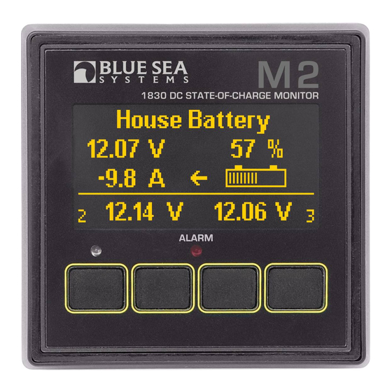
Example Screens From PN 1838 AC Multimeter When an M2 Meter is initially powered up, it will display the Blue Sea Systems Logo,its serial number and its Software revision. After a couple of seconds, the unit will display a high-level System Summary screen. -
Page 10: Configuring The Meter
Setting Alarms The M2 Meter family provides monitoring capability of input channels. The meter can monitor Voltage, Current, and Frequency. Alarms are triggered if a channel is above or below a certain user selected threshold value. (Note: not every meter supports every alarm) The following example indicates how to setup an over voltage Alarm. - Page 11 Relay Setup & Control M2 Meters provide an option to control an external relay. The M2 can trigger the relay based on Voltage, Current, or Frequency. These relay options can be set from the Relay Setup menu. To get there, first navigate to the Setup menu. Then scroll to Relay Setup and press the Select button.
- Page 12 Notification The Notification setting controls whether or not a notification is displayed when a relay is activated. Notifications will show which relay threshold was surpassed and for which channel. Scroll to Notification and press Select to change the setting. Press the LEFT ← or RIGHT → arrow buttons to choose either ON or OFF.
-
Page 13: Display Setup
Clearing Relay Notification If the Notification option is set to ON then any time the relay is opened (Normally Off) or closed (Normally On). A message will be displayed on the main screen. Pressing a key will clear this notification. If Silence is set to ON then the relay will be opened (Normally Off) or closed (Normally On). Viewing Relay Status For any active alarm, the parameter will flash if it is displayed. -
Page 14: Version Info
Changing System Labels The M2 allows the user to change the labels that are displayed above each channel. Each channel can have a maximum of 16 characters however in the summary screens only the first 11 or 12 characters of the channel label are displayed. -
Page 15: Software Upgrade
6. Answer Yes to “Are you sure you want to update the Flash?” 7. The red LED on the M2 will rapidly flash for about 10 seconds. 8. If the upgrade was successful, a message with the new software version will be displayed.
Need help?
Do you have a question about the M2 and is the answer not in the manual?
Questions and answers