
Summary of Contents for ZKaccess SmartLPR Access
- Page 1 Installation Guide SmartLPR Access License Plate Recognition Unit All-In-One ZKAccess.com SmartLPR Access Installation Guide...
- Page 2 Safety Precautions IR LIGHTING MODELS LED RADIATION LED PRODUCT RISK GROUP 1 DON'T LOOK DIRECTLY USING OPTICAL INSTRUMENTS (MAGNIFYING GLASSES, LENS OR MICROSCOPES) OPTICAL POWER OUTPUT: 6W ● WAVE LENGHT: 850 nm ● LED PRODUCT CLASS 1M, as to UNE-EN 62471:2009 standard ●...
- Page 3 WHITE LIGHTING MODELS LED RADIATION LED PRODUCT RISK GROUP 2 POSSIBLY HAZARDOUS OPTICAL RADIATION EMITTED FROM THIS PRODUCT DO NOT STARE AT OPERATING LAMP. IT MAY BE HARMFUL TO THE EYE. Exposure hazard values (EHVs) and the hazard distances with optional graphical presentation of distant-dependent EHV: 55,7 sec.
-
Page 4: Table Of Contents
TABLE OF CONTENTS Basic Concepts ......................7 1. Introduction ......................8 1.1. What SmartLPR® Access is ................8 1.2. System description ..................8 1.3. Operating Modes ..................... 9 1.4. Available models .................... 10 1.5. Optional parts ....................12 1.6. Integration ....................12 1.6.1. - Page 5 4.2.2. Input/Output system characteristics ............33 4.3. Focus......................33 4.4. Closing the unit ..................... 34 Configuration ....................... 35 4. Configuration system .................... 36 5.1. Login ......................36 5.2. Lens adjustment .................... 36 5.3.“Multi-unit configuration” ................. 37 5.4. Configure the units ..................38 5.5.
-
Page 6: Basic Concepts
SmartLPR ® Access User Manual Basic concepts Basic Concepts The section provides a basic summary of SmarLPR ® Access main system characteristics such basic system operation ● available models ● different development options ● available communications ● steps prior to installation. ●... -
Page 7: Introduction
SmartLPR ® Access User Manual Basic concepts Introduction 1.1. What SmartLPR ® Access is SmartLPR ® Access is a license plate recognition (LPR1 ) system specially designed to be used in access lanes with barriers. SmartLPR ® Access is based on an All-In-One concept, which embeds in a single equipment all the operations needed for license plate recognition (image acquisition and further processing), so that installation becomes much easier compared to systems using separate capture and process units. -
Page 8: Operating Modes
SmartLPR ® Access User Manual Basic concepts Please follow the indications and note you don't need to open the unit in order to install and configure it and be aware that the warranty will be immediately voided if the unit presents signs of manipulations applied in the attempt to open it. -
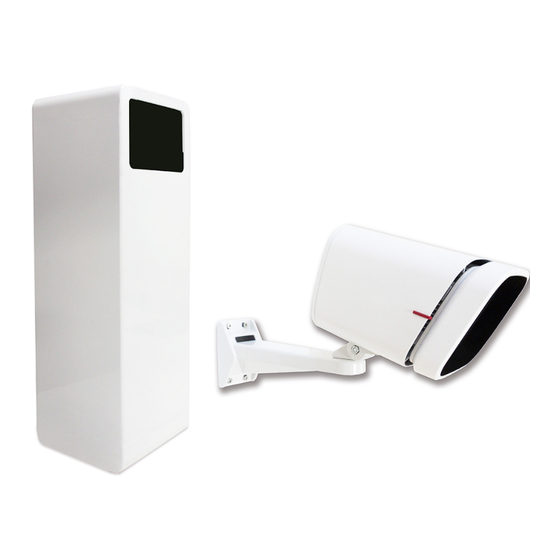
Page 9: Available Models
SmartLPR ® Access User Manual Basic concepts 4. Pre-arming loop: SmartLPR ® Access directly receives from a loop installed at the beginning of the lane a signal indicating the recognition must start. When the client application sends a recognition request, SmartLPR ®... - Page 10 SmartLPR ® Access User Manual Basic concepts Camera housing: horizontal camera-like housing, useful when the unit must be fixed ● on the wall or ceiling. 1.4.2. Type of lighting Infrared: black and white image format; equipped with infrared light source. ●...
-
Page 11: Optional Parts
SmartLPR ® Access User Manual Basic concepts 1.4.5. Temperature control Without temperature control module: does not provide protection against extreme ● temperatures. With temperature control module: provides protection against extreme temperatures ● and increases its working range. All models are absolutely compatible (at software level) between them and can be combined in the same installation without any problem. -
Page 12: Access Control, White Lists And Wiegand Protocol
SmartLPR ® Access User Manual Basic concepts Function library in C: dynamically linked library for Windows and GNU/Linux that ● provides a function oriented vision of the system. It transparently manages simultaneous communication with various units and allows programming with C while keeping the high level vision provided by the C++ library. - Page 13 SmartLPR ® Access User Manual Basic concepts unit) which can be updated. The client software is always backwards compatible, meaning you can control all SmartLPR ® versions by using the latest one. Each version number of software/firmware is composed of three numbers (for example 2.4.5): In order to know if a firmware update is compatible with your unit, the current version must be checked and compared with the update version.
-
Page 14: Installation
® Access User Manual Installation SmartLPR Installation This section describes how a SmartLPR ® unit is installed from the moment you plan its placement and until it is finally installed. Quercus Technologies... -
Page 15: Installation Of The Unit
® Access User Manual Installation SmartLPR Installation of the unit The correct operation of any LPR system depends on several external factors. Most of these factors can be optimized if considered during the access lanes layout. Quercus Technologies can guarantee an optimum operation of a SmartLPR ®... -
Page 16: Front Plate Capture
® Access User Manual Installation SmartLPR 2.1. Front plate capture 2.1.1. Front plate capture Recommended 2,5 – 3 m Minimum distance 1,5 m Maximum distance The unit must always be installed at 2,5-3m from the barrier. In this type of installation, the LPR unit captures the license plate when the vehicle arms the presence loop installed in line with the ticket dispenser, as shown in the drawing below. -
Page 17: Queue Management In Installations For Front Plate Capture
® Access User Manual Installation SmartLPR 2.1.2. Queue management in installations for front plate capture Queues are usually formed in barrier-controlled accesses, thus you have to make sure that the license plate of the arriving vehicle will be fully seen. To this end, we recommend the use of two metal loops: the second one should be placed under the barrier so that when the vehicle is no longer on it, it won't appear in the image. -
Page 18: Rear Plate Capture
® Access User Manual Installation SmartLPR 2.2. Rear plate capture 2.2.1. Rear plate capture In installations for rear plate capture, we recommend installing a presence detector before the one installed in line with the ticket dispenser. In this way you make sure that the camera captures the license plate when the vehicle releases the first sensor (called “LPR sensor”... -
Page 19: Ceiling Installation
® Access User Manual Installation SmartLPR 2.3. Ceiling installation In case the unit must be installed on the ceiling, the minimum horizontal distance from the unit to the license plate must be of 5 m and the angle between the unit and the floor must not exceed 30º. -
Page 20: Supplied Material
® Access User Manual Installation SmartLPR Supplied material 3.1. List of materials for cabinet models 1. Recognition unit 2. Quick start guide 3. Sun shield (optional) 4. Base fixing screws 5. 3 connectors (power, signals, network) Quercus Technologies... - Page 21 ® Access User Manual Installation SmartLPR Quercus Technologies...
-
Page 22: List Of Materials For Camera Housing Models
® Access User Manual Installation SmartLPR 3.2. List of materials for camera housing models 1. Recognition unit 2. 3 external connectors (power, signals, network) 3. Quick start guide 3.3. Optional parts for camera housing models 1. Wall support 2. Floor / ceiling kit (floor/ceiling bracket + iron sheet + spacer) 3. -
Page 23: Unit Installation
® Access User Manual Installation SmartLPR 4.1. Unit installation 4.1.1. Cabinet housing unit installation Open the unit. Use a standard triangular 8mm wrench / 8mm triangular spanner. Pass the cables inside the cabinet. 4.2. Wiring and pinouts Connect the cables to their pin. (check Place the unit so that the glass should point approximately to the center of the lane. -
Page 24: Camera Housing Unit Installation
® Access User Manual Installation SmartLPR Fix the unit to the floor. Let the screws untighten as you'll have to rotate the cabinet to correctly adjust the image. (see section 4.3. Focus). Place the sun shield. To know how to make these cables, go to 4.2. Wiring and pinouts. 4.1.2. -
Page 25: Wall Installation
® Access User Manual Installation SmartLPR 4.1.2.1 Wall installation Place the unit on the bracket. Place the bracket on the wall. 4.1.2.2. Ceiling installation Remove the iron plate of the swivel head and keep the screws for the final step. Place the swivel head on the vertical bracket. -
Page 26: Floor Installation
® Access User Manual Installation SmartLPR Fix the iron sheet on the unit using the spacer provided. Place the unit on the bracket, keeping the longer side of the bracket in the front. Install the bracket on the ceiling. 4.1.2.3. Floor installation Remove the iron sheet from the swivel head (you will... -
Page 27: Vertical Pole Installation
® Access User Manual Installation SmartLPR Place the unit on the bracket keeping the longer side of the bracket in the front. Fix the unit to the floor. 4.1.2.4. Vertical pole installation Place the unit on the wall bracket. Fix the wall bracket to the pole bracket. Quercus Technologies... -
Page 28: Common Procedures
® Access User Manual Installation SmartLPR Place the assembly obtained on the vertical pole. 4.1.2. Common procedures This section describes all the procedures common to all the installation methods of the camera housing models (ceiling, wall, mast, floor, etc.). 1. Connect the network cable. 2. - Page 29 ® Access User Manual Installation SmartLPR Unscrew the main body of the connector. Pass the cables through the cable glands and through the main body of the connector. Connect the cables to their pin (rear view) Pin Meaning +12V Tighten the main body of the connector. Tighten the cable glands at the bottom of the connector.
- Page 30 ® Access User Manual Installation SmartLPR Pass the cables through the cable glands and through the main body of the connector. Connect the cables to their pin (rear view) Pin Meaning Neutral Line Protective Earth Tighten the main body of the connector. Tighten the cable glands at the bottom of the connector.
- Page 31 ® Access User Manual Installation SmartLPR Pass the cables through the cable glands and through the boot. Crimp the RJ-45 connector. Place the RJ-45 connector inside the boot and close it. Please note: the boot is essential in order to assure the leak tightness of the unit.
-
Page 32: Input/Output System Characteristics
® Access User Manual Installation SmartLPR Pin Meaning OUT1 + 12V Wiegand D0 Wiegand D1 Tighten the main body of the connector. Tighten the cable glands at the bottom of the connector. Once you have all the cables made, connect them to the unit and tighten firmly. For the camera housing models, seal the connectors you did not use with the sealing cap supplied. -
Page 33: Focus
® Access User Manual Installation SmartLPR 4.3. Focus To adjust the camera follow the next steps: 1. Connect the unit to power. 2. Connect the crossover cable to the unit and the laptop. 3. Switch on the laptop and go to the web browser. 4. -
Page 34: Closing The Unit
® Access User Manual Installation SmartLPR zoom (the license plate must be in the center and the image sharp). Check section 5.2. Lens adjustment to know how to correctly use these adjustment options. Adjust the zoom and the focus until you get a license plate at a ¼ scale to the whole image. (The size of the license plate you see on the image should have approximately 140-150 pixels from first to last character.) (for normal resolution model) 9. -
Page 35: Configuration
® Access User Manual Configuration SmartLPR Configuration Quercus Technologies... -
Page 36: Configuration System
® Access User Manual Configuration SmartLPR Configuration system Each SmartLPR ® Access unit has an embedded configuration web from where you can configure all the units in an installation at the same time. To configure the units in an installation you must follow the next steps: LOGIN LENS ADJUST MULTI-UNIT CONFIGURATION... -
Page 37: Multi-Unit Configuration
® Access User Manual Configuration SmartLPR 5.3. “Multi-unit configuration” Press on “Multi-unit configuration” menu to see all the units found in the system. Click on the icon that represents a camera to adjust the focus/zoom of each unit; once you have adjusted all the units, go back to “Multi-unit configuration”... -
Page 38: Configure The Units
® Access User Manual Configuration SmartLPR 5.4. Configure the units To configure each unit go to the button menu at the top left corner of the screen. Click on "Configuration" . There are various submenus with different configuration variables. It is very important to click "Save changes"... - Page 39 ® Access User Manual Configuration SmartLPR RECOGNITION: configuration of the recognition engine of the unit. ● WorkingMode: the operation mode of the unit. Possible values: ● Software: it is the central system that determines when the plate recognition ● should take place. Hardware: the unit detects vehicle movements and determines when the ●...
- Page 40 ® Access User Manual Configuration SmartLPR OSD: ● Main options: Parameters that configure the information to be overprinted as text ● straight on the image. Active: sets the OSD system active or not. ● Position: image position where the text should be displayed. ●...
-
Page 41: Apply Changes
® Access User Manual Configuration SmartLPR 5.5. Apply changes To apply the configuration press "Apply" in the "Apply changes" menu. You can select the units you want to apply the changes to and also the changes you want to apply. The units need to restart to make the new settings operational and this can take up to 1 minute. -
Page 42: Advanced Concepts
SmartLPR ® Access User Manual Advanced Concepts Advanced concepts Quercus Technologies... -
Page 43: Firmware Update
SmartLPR ® Access User Manual Advanced Concepts 6.1. Firmware update To update the firmware means to incorporate in the unit newer versions of SmartLPR system in order either to fix some errors or to include new functionalities. 6.1.1. Steps required before updating Before installing an update, you first have to make it available on the unit. -
Page 44: The Behavior Of The Control Led
SmartLPR ® Access User Manual Advanced Concepts Once the update is finished, a window with the result of the update will appear, and the unit will restart, now operating with the new firmware. Updating the unit firmware is a delicate operation. If you still have doubts about the process, contact Quercus Technologies support department who will guide you through so that you can carry out the update safely. -
Page 45: Osd
SmartLPR ® Access User Manual Advanced Concepts 6.3. OSD Every OSD line has both text and variables which will be replaced by a specific value in each recognition; a line can have up to 63 characters. You will find a description of the available variables at the last page of the present paper. - Page 46 SmartLPR ® Access User Manual Advanced Concepts microseconds %u) Example 2: hour with millisecond accuracy. $timestamp( %Y/%02T/%02D %02H:%02M:%02S.%03m) Examples Configuration 1: Moment: $timestamp( %Y/%02T/%02D %02H:%02M:%02S.%03m).” Possible result 1: Moment: 2014/05/18 13:01:20.711.” Configuration 2: “Unit $unitId(), Vehicle $carId() - $license().” Possible result 2: “Unit 35, Vehicle 27 –...
- Page 47 SmartLPR ® Access User Manual Advanced Concepts Variables available in OSD Description Identifier of the variable Format Vehicle identifier. carId Text Identifier of the trigger that led to the recognition. TriggerId Text Shows if the license matches any known grammar. grammarOk Text Character or Characters identifying the country of the...
-
Page 48: Annexes
SmartLPR ® Access User Manual Annexes Annexes Quercus Technologies... -
Page 49: Annex A: Table Of Product References And Technical Specifications
● ● SmartLPR Access A CL WL AC CT 07000416 ● ● ● ● ● ● SmartLPR Access NA A CL WL AC CT 07000417 ● ● SmartLPR Access A DC 07000401 ● ● ● SmartLPR Access NA A DC 07000418 ●... - Page 50 ● ● SmartLPR Access I CL WL AC CT 07000434 ● ● ● ● ● ● SmartLPR Access NA I CL WL AC CT 07000435 ● ● SmartLPR Access I DC 07000436 ● ● ● SmartLPR Access NA I DC 07000437 ●...
- Page 51 ● ● SmartLPR Access C CL WL AC CT 07000466 ● ● ● ● ● ● SmartLPR Access NA C CL WL AC CT 07000467 ● ● SmartLPR Access C DC 07000451 ● ● ● SmartLPR Access NA C DC 07000468 ●...
-
Page 52: Annex B: Ce Certificates
8. Annex B: CE Certificates Products with Certificate (see Technical Specifications Datasheets www.downoloads.quercus.biz) have Class A category. In a domestic environment this product may cause radio interference, in which case the user has to take adequate actions. Warning This is a class A product. In a domestic environment this product may cause radio interference in which case the user may be required to take adequate measures. - Page 53 SmartLPR Access NA C WL AC SmartLPR Access NA C WL AC CT SmartLPR Access NA C CL WL AC SmartLPR Access NA C CL WL AC CT Conforms to the following Product Specifications and Regulations: Directive: Electromagnetic Compatibility Directive (EMC) 2004/108/EC Applicable standards: EN 55024:2010 “Information technology equipment.
- Page 54 SmartLPR Access NA C WL DC SmartLPR Access NA C WL DC CT SmartLPR Access NA C CL WL DC SmartLPR Access NA C CL WL DC CT Conforms to the following Product Specifications and Regulations: Directive: Electromagnetic Compatibility Directive (EMC) 2004/108/EC Applicable standards: EN 55024:2010 “Information technology equipment.
- Page 55 SmartLPR Access NA A WL AC SmartLPR Access NA A WL AC CT SmartLPR Access NA A CL WL AC SmartLPR Access NA A CL WL AC CT SmartLPR Access NA I WL AC SmartLPR Access NA I WL AC CT...
- Page 56 SmartLPR Access NA A WL DC SmartLPR Access NA A WL DC CT SmartLPR Access NA A CL WL DC SmartLPR Access NA A CL WL DC CT SmartLPR Access NA I WL DC SmartLPR Access NA I WL DC CT...
- Page 57 SmartLPR Access User Manual Annexes ® Place and date: Reus, 13 of May of 2015 Signed by: Albert Mateu López R&D Director Quercus Technologies...
-
Page 58: Annex C: Fcc Certificate
SmartLPR Access User Manual Annexes ® 9. Annex C: FCC Certificate Warning This equipment (see Technical Specifications Datasheets at www.downoloads.quercus.biz) has been tested and found to comply with the limits for a Class A digital device, pursuant to part 15 of the FCC Rules. These limits are designed to provide reasonable protection against harmful interference when the equipment is operated in a commercial environment. - Page 59 SmartLPR Access NA A WL AC SmartLPR Access NA A WL AC CT SmartLPR Access NA A CL WL AC SmartLPR Access NA A CL WL AC CT SmartLPR Access NA I WL AC SmartLPR Access NA I WL AC CT...
- Page 60 SmartLPR Access User Manual Annexes ® R&D Director Quercus Technologies...
- Page 61 SmartLPR Access NA A WL DC SmartLPR Access NA A WL DC CT SmartLPR Access NA A CL WL DC SmartLPR Access NA A CL WL DC CT SmartLPR Access NA I WL DC SmartLPR Access NA I WL DC CT...
- Page 62 SmartLPR Access User Manual Annexes ® Quercus Technologies...
- Page 63 SmartLPR Access NA C WL AC CT SmartLPR Access NA C CL WL AC SmartLPR Access NA C CL WL AC CT To which this declaration relates is in conformity with the following specifications: FCC CFR47 Part 15, subpart B, Class A Digital Device.
- Page 64 SmartLPR Access NA C WL DC CT SmartLPR Access NA C CL WL DC SmartLPR Access NA C CL WL DC CT To which this declaration relates is in conformity with the following specifications: FCC CFR47 Part 15, subpart B, Class A Digital Device.
- Page 65 Fax: (862) 204-5906 www.zkaccess.com © Copyright 2014. ZKTeco Inc. ZKTeco Logo and ZKAccess Logo are registered trademarks of ZKTeco or a related company. All other product and company names mentioned are used for identification purposes only and may be the trademarks of their respective owners. All specifications are subject to change without notice.
Need help?
Do you have a question about the SmartLPR Access and is the answer not in the manual?
Questions and answers