Table of Contents
Advertisement
Advertisement
Table of Contents

Related Manuals for Nokta MAKRO Racer 2


Summary of Contents for Nokta MAKRO Racer 2
- Page 2 WARNINGS RACER 2 is a state-of-the-art electronic device. Do not assemble or operate the device before reading the user manual. Do not keep the device and search coil under extremely low and high temperatures for extended periods.
-
Page 3: Table Of Contents
Table of Contents Assembly ................................. General Description of the Device ................ Battery Details ............................Display ................................Correct Use ..............................Quick Guide ..............................Menu 7-12 ................................Modes 13-14 ..............................Ground Balance 15-18 ........................Gain, iSAT and Threshold 18-19 ..................Target ID and ID Filter 20-21 .................... -
Page 4: Assembly
Assembly Insert the washers as shown on the telescopic shaft. Install the telescopic shaft to its location on the search coil. Secure by tightening the screw and nut. Loosen the twist lock before mounting the telescopic shaft to the upper rod. Press down the pin and engage the pieces together and tighten the twist lock after the pin is clicked into the hole. -
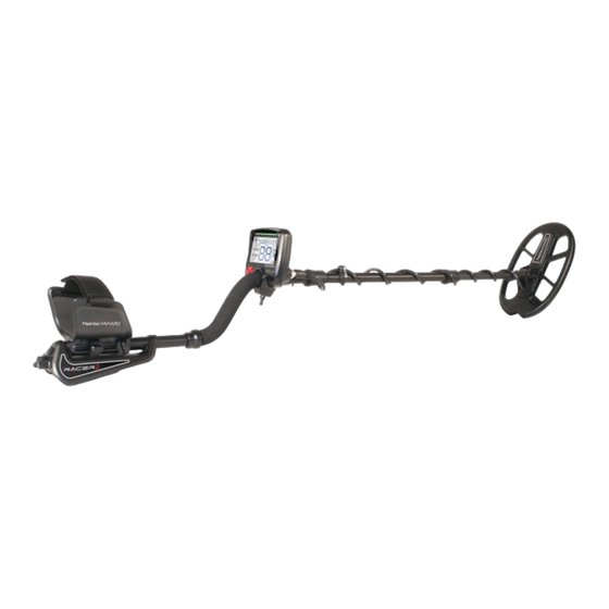
Page 5: General Description Of The Device
General Description of the Device Display showing all settings and information Keypad for navigation among menu options and changing the device settings Ground balance and pinpoint trigger Speaker Battery compartment cover On /Off and volume adjustment button Wired headphone jack Search coil connector socket LED flashlight Page 2... -
Page 6: Battery Details
Battery Details The device is supplied with 4 pieces of AA Alkaline batteries. To remove the battery compartment cover, press on the latch and pull out. Insert the batteries observing correct polarity of + (plus) and - (minus). The device can be used for approximately 20-25 hours when the batteries are fully charged. -
Page 7: Display
Display Menu providing access to all settings of the device Cursor indicating the ID of the detected target and its position on the ID scale. It also indicates the IDs masked by ID FILTER and NOTCH FILTER as well as the tone breakpoints. Target ID scale Search mode indicator Section which shows the TARGET ID during search, the ground balance... -
Page 8: Correct Use
Correct Use Incorrect Handling Correct Handling Incorrect Use Correct Use Incorrect Use Correct Use Page 5... -
Page 9: Quick Guide
Quick Guide Assemble the device as per the instructions on page 1. Insert the batteries by paying attention to +/- polarity. Rotate the on/off switch located behind the device clockwise to turn on the device. This switch also adjusts the volume. When the device is turned on, it will start in the Three Tone mode. -
Page 10: Menu
5 search modes adapted to different ground conditions and target types are offered by RACER 2. Names of the search modes are defined as ALL METAL, TWO TONE, THREE TONE, BEACH and DEEP on the menu screen. You can easily switch between the modes by using the direction keys during your search. - Page 11 Menu ID FILTER is the ability of the device to ignore all metals below a certain TARGET ID. In the ID FILTER process, the filtered ID range is shown with lines on the ID scale and every 2 consecutive IDs are represented with 1 line. For example, if you set the ID FILTER to 30, 15 lines will be shown between the 0-30 ID range on the scale and the device will not produce a warning tone for any metals with IDs between 0-30.
- Page 12 Menu NOTCH FILTER adjustment applies to the selected search mode only. The change does not affect the other modes. Since there is no discrimination in the ALL METAL mode, this setting is inactive in this mode. IRON AUDIO It adjusts or turns off the volume of the low iron tone. IRON AUDIO range is 00-10.
- Page 13 Menu ALL METAL ONLY THRESHOLD This setting is used to adjust the humming sound, referred to as the threshold sound, which is continuously heard in the background in the All Metal mode. It is used to increase the target signal, in other words, the depth of the device. For more details, please read Gain, Threshold and iSAT section.
- Page 14 Factory Default /Save (FD/Save) With the FD/Save feature of the RACER 2, you can save your settings or restore factory defaults. Save function saves all settings except for the ground balance and tracking. The device starts in the last mode where the save function was performed. For example, you changed the settings of both the All Metal mode and the Deep Mode and you saved the settings while in the Deep mode.
- Page 15 Menu To restore factory defaults, select FD/Save on screen and press the minus (-) button. FD will be displayed. To confirm, pull the trigger once and release. FD will stay on screen for a short period of time and it will disappear when the process is completed. Other Settings Not Shown on Screen FREQ.
-
Page 16: Modes
MODES All Metal It is the deepest mode of the device. Different than the other modes, this mode features a threshold tone which is continuously heard in the background. The device does not discriminate targets while in the All Metal mode and detects all targets (metal, mineralized rocks etc.). - Page 17 It is recommended to modify this value according to the type of target. Beach Mode It is the special mode of RACER 2 developed for conductive grounds (wet sand beach, grounds with alkali soil etc.). The feature of this mode is its ability to ignore iron and similar targets in this group and to perform ground balance on any type of ground.
-
Page 18: Ground Balance
Ground Balance Ground balance can be performed in three ways in RACER 2: Automatic, Manual and TRACKING. If the trigger is pushed forward while performing automatic or manual ground balance, the device will switch to the All Metal mode automatically on the background without any indication to the user, regardless of the selected search mode. - Page 19 RACER 2 is designed to allow for automatic ground balancing conveniently on any type of ground. Therefore, it is recommended to perform automatic ground balance upon start up.
- Page 20 Ground Balance The device will return to the main screen automatically after a moment upon completion of ground balance. To return immediately, just pull and release the trigger once. IMPORTANT! Experienced detectorists adjust the ground balance setting to little positive response (weak but audible sound is produced when moving the search coil closer to ground).
-
Page 21: Gain, Isat And Threshold
Ground Balance Important Details Concerning Ground Balance 1) Upon start up, the ground balance value is set as 90. The device can perform ground balance automatically within the range of 40-90 in all modes and 0-90 in the Beach mode. 2) If the ground mineralization is too low, automatic ground balance may fail to work in other modes except for the Beach mode. - Page 22 Gain, iSAT and Threshold It is recommended for average users to leave this setting at its default value and for experienced users to adjust to the highest level where they can still hear the weak target signals. You cannot search in the All Metal mode without ground balancing. Changes that occur in the ground effect after ground balancing cause false signals or disruption in the threshold hum.
-
Page 23: Target Id And Id Filter
Target ID and ID Filtering As explained before, target ID is a 2 digit number defining the target, produced by the metal detector while the search coil goes over a target The number is shown on the display as TARGET ID. In some cases, the device may produce multiple IDs for the same target. - Page 24 Target ID and ID Filtering It may take some time and experience to utilize the Target ID feature in your search area because Target IDs as well as the depths the IDs are generated by different brands and models of detectors are also different. As indicated before, ID FILTER feature is the ability of the device to perform search without producing warning tones for unwanted metals.
-
Page 25: Pinpoint
Pinpoint is to find the center or the exact location of a detected target. RACER 2 is a motion detector, in other words, you are required to move the search coil over the target or the target over the search coil in order for the device to detect the target. The pinpoint mode is a non-motion mode. -
Page 26: Target Distance
''IS'' will be displayed. Swinging Speed and Target Identification RACER 2 is a detector with very high detecting speed. When you detect a target with RACER 2, you should make wider passes instead of narrowing the sweeps and making quick sweeps over the target like in other metal detectors, in order to receive an accurate ID from the target. -
Page 27: Magnetic Mineralization Indicator
Magnetic Mineralization Indicator The Magnetic Mineralization Indicator consists of 5 levels. The indicator is shown empty at low mineral levels during search and at start up. In areas where the magnetic mineral level is high, the indicator level increases according to the intensity. This measurement can be summarized as the level of magnetic property and intensity of the ground. -
Page 28: Tracking And Effects Of Rocks
Metals Under Rocks RACER 2 increases the possibility of detecting metal targets under mineralized rocks through the proper adjustment of your settings. The combined effect created by the rock and metal together is lower than the effect that the metal creates by itself and the displayed ID will be different than the metal's expected ID. -
Page 29: Searching In Shallow Water And Beach
As explained before, salt water and alkali grounds are significantly conductive and cause effects similar to iron in detectors. RACER 2’s Beach mode is specially designed for such conditions. You can perform your search easily using the Beach mode without requiring any special settings. -
Page 30: Messages
Messages Warning messages are shown on the bottom of the display during search. Messages that may appear are as follows: Saturation It appears on the display simultaneously with the overload alarm sounding like a siren. This happens when the search coil encounters a near surface or a very large object. The device reverts back to normal operation if you lift the coil up. -
Page 31: Technical Specifications
Technical Specifications Operating Principle VLF Induction Balance Operating Frequency 14 kHz (+/- 100 hz bandwidth) Audio Frequencies 100 Hz - 700Hz adjustable Search Modes 5 (All Metal/Two Tone/Three Tone/Beach/Deep) Iron Audio Tone Break Notch Filter Ground Balance Automatic / Manual / Tracking Pinpoint Available Frequency Shift...
Need help?
Do you have a question about the Racer 2 and is the answer not in the manual?
Questions and answers
How do I eliminate finding pull tabs that show 33 on the display screen?
To avoid detecting pull tabs that show 33 on the Nokta MAKRO Racer 2, use the NOTCH FILTER feature:
1. Open the NOTCH FILTER menu.
2. Use the plus (+) or minus (-) button to navigate to ID 33.
3. Pull and release the trigger once to reject ID 33. It will be marked with a line on the display.
4. If you want to undo this later, return to the NOTCH FILTER menu and remove the rejection.
This will filter out objects with an ID of 33 from detection.
This answer is automatically generated
@Mr. Anderson How do I get rid of chatter at first start up?
Is there a way to adjust sensitivity up or down?
The sensitivity on the Nokta MAKRO Racer 2 can be adjusted using the gain setting in discrimination modes. To adjust it:
1. Perform ground balance while the gain is at its default setting.
2. Hold the search coil still or swing it over the ground at search height.
3. If the device receives noise, reduce the gain.
4. If there is no noise, gradually increase the gain until no popping sound occurs.
5. If the device starts receiving noise during searching, reduce the gain gradually.
6. If the ground is highly mineralized and the coil overloads, decrease the gain until the "Saturation" message disappears from the screen.
This adjustment helps ensure stable operation and optimal depth detection.
This answer is automatically generated