
Related Manuals for Allen-Bradley 1769-SDN


Summary of Contents for Allen-Bradley 1769-SDN
- Page 1 Compact I/O 1769-SDN DeviceNet Scanner Module 1769-SDN User Manual Allen-Bradley Drives...
- Page 2 In no event will Allen-Bradley be responsible or liable for indirect or consequential damage resulting from the use or application of these products.
- Page 3 1. Go to http://www.ab.com 2. Click on Product Support (http://support.automation.rockwell.com) Your Questions or Comments on this Manual If you find a problem with this manual, please notify us of it on the enclosed How Are We Doing form. Allen-Bradley Drives...
-
Page 5: Table Of Contents
Communicating with Your Slave Devices ....1-4 1769-SDN Module Data Tables ..... 1-5 RSNetWorx Software as a Configuration Tool . - Page 6 Controller ........6-10 Calculating Maximum I/O Sizes for the 1769-SDN Scanner Module.
- Page 7 If you do not, obtain the proper training before using this product. Purpose of this Manual This manual is a reference guide for Compact I/O 1769-SDN DeviceNet Scanner Module. It describes the procedures you use to install, program, and troubleshoot your module. This manual: •...
- Page 8 Read this Document Document Number Information on understanding and applying micro controllers. MicroMentor 1761-MMB Information on mounting and wiring the 1769-SDN module. Compact I/O 1769-SDN DeviceNet Scanner 1769-IN060 Module Installation Instructions Information on RSNetWorx for DeviceNet (catalog number RSNetWorx for DeviceNet Technical Data 9398-DNETTD 9357-DNETL3).
- Page 9 • Bulleted lists such as this one provide information, not procedural steps. • Numbered lists provide sequential steps or hierarchical information. • Italic type is used for emphasis. This symbol identifies helpful tips. Allen-Bradley Drives Publication 1769-UM009B-EN-P - May 2002...
- Page 10 If you need to contact Rockwell Automation for technical assistance, please review the Troubleshooting information in chapter 8 first. Then call your local Allen-Bradley distributor or Rockwell Automation Technical Support. (phone 440-646-5800) For Rockwell Software products, use the following contact information: •...
-
Page 11: What You Need To Know
This chapter provides an overview of communication between the CompactLogix and MicroLogix 1500 programmable controllers and DeviceNet devices via the 1769-SDN scanner module. The configuration data tables and the RSNetWorx for DeviceNet screens and windows used to configure the data tables are also described. -
Page 12: Identify Module Features
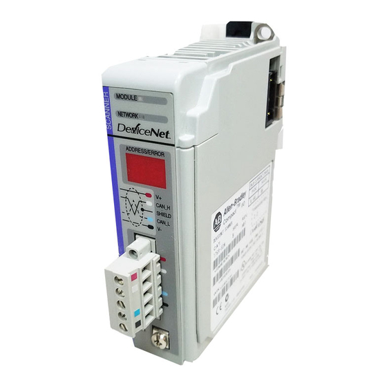
Overview Identify Module Features Use the following figure to identify the features of the scanner. Table 1.1 Item Description bus lever (with locking function) upper DIN rail latch lower DIN rail latch upper panel mounting tab lower panel mounting tab Module and Network status LEDs Address and Error numeric display grounding screw... -
Page 13: What Your Scanner Does
In a typical configuration, the scanner acts as an interface between DeviceNet devices and the programmable controller. DeviceNet Network PC with RSNetWorx for DeviceNet software CompactLogix Controller with MicroLogix 1500 Controller with 1769-SDN Scanner Module 1769-SDN Scanner Module 1770-KFD PC Communication Module DANGER DANGER... -
Page 14: Communicating With Your Slave Devices
Overview Communicating with Your The scanner communicates with devices via strobe, poll, change of state, and/or cyclic I/O messages. It uses these messages to solicit data Slave Devices from or deliver data to each device. Data received from the devices, or input data, is organized by the scanner and made available to the controller. -
Page 15: 1769-Sdn Module Data Tables
Overview 1769-SDN Module Data To manage the flow of data between your controller and network devices, the scanner uses input and output data images to transfer Tables data, status and command information between the scanner and the controller. The basic structure is shown below. See Chapter 5 for more detailed information. -
Page 16: Rsnetworx Software As A Configuration Tool
For more detailed information, see: • Chapter 4, Configuring the DeviceNet Network • Chapter 6, Using the 1769-SDN Scanner Module with CompactLogix Controllers • Chapter 7, Using the 1769-SDN Scanner Module with MicroLogix Controllers Publication 1769-UM009B-EN-P - May 2002... - Page 17 The main RSNetWorx screen. To browse the network, click on the Online button and select the driver. To access the 1769-SDN Scanner Module, double-click on the 1769-SDN icon. To access the scanlist, Move the device into click on the Scanlist tab.
- Page 18 Overview Notes: Publication 1769-UM009B-EN-P - May 2002...
-
Page 19: Chapter 2 Before You Begin
Chapter Quick Start for Experienced Users Before You Begin This chapter can help you to get started using the 1769-SDN scanner module. We base the procedures here on the assumption that you have an understanding of Allen-Bradley controllers. You should... -
Page 20: What You Need To Do
Table 2.1 Module 5V dc 24V dc 1769-SDN 440 mA 0 mA The module cannot be located more than 4 modules away from the system power supply. b. If you are not familiar with Compact I/O and DeviceNet limitations, see System Planning on page 3-5. - Page 21 Be sure to observe minimum spacing guidelines on page 3-7 for adequate ventilation. Ground the module and complete DeviceNet wiring. Chapter 3 EXAMPLE Installation and Wiring Apply power to the system. Chapter 3 EXAMPLE Installation and Wiring Chapter 8 Troubleshooting Allen-Bradley Drives Publication 1769-UM009B-EN-P - May 2002...
- Page 22 EXAMPLE Configuring the DeviceNet Network Use RSLinx to configure drivers. Chapter 4 EXAMPLE Configuring the DeviceNet Network Use RSNetWorx to configure the 1769-SDN scanner module and the DeviceNet Devices. Chapter 4 EXAMPLE Configuring the DeviceNet Network Chapter 5 DeviceNet I/O Image...
- Page 23 Module status is reported by the LEDs and numeric display on the front of the module. The information is also stored in the module’s input data file, so these bits can be used in your control program to flag an error. Allen-Bradley Drives Publication 1769-UM009B-EN-P - May 2002...
- Page 24 Quick Start for Experienced Users Notes: Publication 1769-UM009B-EN-P - May 2002...
-
Page 25: Compliance To European Union Directives
Chapter Installation and Wiring This chapter describes how to install and wire the 1769-SDN scanner module. The following table describes what this chapter contains and where to find specific information. For information about See page Compliance to European Union Directives... -
Page 26: Power Requirements
Programmable Controllers, Part 2 – Equipment Requirements and Tests. For specific information required by EN61131-2, see the appropriate sections in this publication, as well as the following Allen-Bradley publications: • Industrial Automation, Wiring and Grounding Guidelines for Noise Immunity, publication 1770-4.1 •... -
Page 27: General Considerations
Over Voltage Category II is the load level section of the electrical distribution system. At this level transient voltages are controlled and do not exceed the impulse voltage capability of the product’s insulation. Allen-Bradley Drives Pollution Degree 2 and Over Voltage Category II are International Electrotechnical Commission (IEC) designations. - Page 28 Installation and Wiring Prevent Electrostatic Discharge Electrostatic discharge can damage integrated circuits ATTENTION or semiconductors if you touch the bus connector pins. Follow these guidelines when you handle the module: • Touch a grounded object to discharge static potential. • Wear an approved wrist-strap grounding device. •...
-
Page 29: System Planning
• Consider the number of words of I/O data the host controller supports. For more information on planning your DeviceNet network, refer to the DeviceNet Cable System Planning and Installation Manual, publication DN-6.7.2. Allen-Bradley Drives Publication 1769-UM009B-EN-P - May 2002... -
Page 30: System Assembly
Installation and Wiring System Assembly The module can be attached to an adjacent controller, power supply, or I/O module. For mounting instructions, see “Panel Mounting” on page 3-8, or “DIN Rail Mounting” on page 3-10. To work with a system that is already mounted, see “Replacing a Single Module within a System”... -
Page 31: System Mounting
Allow 50 mm (2 in.) of space on all sides for adequate ventilation, as shown below: Side Side Host Controller Bottom Allow at least 110 mm (4.33 in.) of enclosure depth to accommodate the module and the DeviceNet connector. Allen-Bradley Drives Publication 1769-UM009B-EN-P - May 2002... - Page 32 Installation and Wiring Panel Mounting Mount the module to a panel using two screws per module. Use M4 or #8 panhead screws. Mounting screws are required on every module. Panel Mounting Using the Dimensional Drawing NOTE: All dimensions are in mm (inches). Hole spacing tolerance: ±0.4 mm (0.016 in.). Compact I/O with CompactLogix Controller and Power Supply 50 mm 35 mm...
- Page 33 If mounting more modules, mount only the last one of this group and put the others aside. This reduces remounting time during drilling and tapping of the next group. 7. Repeat steps 1 to 6 for any remaining modules. Allen-Bradley Drives Publication 1769-UM009B-EN-P - May 2002...
-
Page 34: Replacing The Scanner Module Within A System
3-10 Installation and Wiring DIN Rail Mounting The module can be mounted using the following DIN rails: 35 x 7.5 mm (EN 50 022 - 35 x 7.5) or 35 x 15 mm (EN 50 022 - 35 x 15). Before mounting the module on a DIN rail, close the DIN rail latches. -
Page 35: Field Wiring Connections
Use a #14 AWG wire to make this connection. Refer to Industrial Automation Wiring and Grounding Guidelines, Allen-Bradley Drives Allen-Bradley publication 1770-4.1, for additional information. Publication 1769-UM009B-EN-P - May 2002... -
Page 36: Scanner Module Power-Up
3. Screw the removable connector to the scanner case with the upper and lower mounting screws. Screw torque is 0.6 to 0.7 Nm (5 to 6 in-lbs). If the 1769-SDN is the first or last device connected IMPORTANT to the DeviceNet network trunkline, be sure to add a termination resistor (120 Ω... -
Page 37: Chapter 4 Software Versions
See page Software Versions Installing the Software Using RSLinx to Configure Your DeviceNet Driver Using RSNetWorx to Configure the 1769-SDN’s Scanlist Software Versions The following table lists the software and revision level required to operate with the 1769-SDN scanner module. -
Page 38: Installing The Software
Configuring the DeviceNet Network Installing the Software Install RSLinx and RSNetWorx. For both of these software packages: 1. Insert the software CD-ROM in the drive. The CD-ROM supports Windows Autorun. If you have Autorun configured, the installation will automatically start when you insert the CD-ROM in your drive. - Page 39 The Driver Configuration window will appear. Your driver setup will depend on your particular system setup (COM port, baud rate, node address). Choose the appropriate settings for your system. We used the settings shown at right. Allen-Bradley Drives Publication 1769-UM009B-EN-P - May 2002...
-
Page 40: Using Rsnetworx To Configure The 1769-Sdn's Scanlist
RSNetWorx. Using RSNetWorx to This manual assumes a certain level of familiarity with RSNetWorx. For detailed information on RSNetWorx for DeviceNet, please refer to your Configure the 1769-SDN’s software’s documentation. Scanlist Setting Up an Online Connection Follow the procedure below to set up an online connection to the DeviceNet network using the 1770-KFD driver. - Page 41 5. Select your DeviceNet driver and click on OK. You will be prompted to upload or download devices before going online. Allen-Bradley Drives Publication 1769-UM009B-EN-P - May 2002...
- Page 42 Configuring the DeviceNet Network 6. Click on OK to upload the devices and go online. RSNetWorx will begin browsing for network devices. When the software is done browsing, your network is displayed on your screen. RSNetWorx performs a single pass browse when you go online or choose the browse feature.
- Page 43 Configuring the DeviceNet Network Setting the 1769-SDN Node Address Once the network browse is complete, the node addresses appear to the right of their icons. If you need to change a module’s node address, use the following procedure. You can use this procedure to change the node address of other devices on the network (e.g., a...
- Page 44 Configuring the DeviceNet Network 2. Click on the Browse button. You will see the Device Selection window. 3. Select the DeviceNet network. The devices on the network will appear in the right panel of the window. Publication 1769-UM009B-EN-P - May 2002...
- Page 45 The default scanner settings are: • baud rate = 125K • node address = 63 5. In the New Device Settings: Node Address box, enter the new node address. 6. Click on Apply and Exit the window. Allen-Bradley Drives Publication 1769-UM009B-EN-P - May 2002...
- Page 46 RSNetWorx. The following screen shows how a DeviceNet network is shown within RSNetWorx. As you can see, node one is a 1769-SDN scanner. To view or modify the scanner’s parameters, double-click on the scanner.
- Page 47 General Tab The following screen shows the properties dialog that RSNetWorx displays for the 1769-SDN scanner module. Available items are accessed through a series of tabs located across the top of the screen. The General tab is the default tab and provides information relative to the module.
- Page 48 This parameter defines the delay time the scanner uses between scans of the DeviceNet network. If you have slave devices configured for Polled behavior in the 1769-SDN’s scanlist, Interscan Delay (ISD) defines the amount of time the scanner waits between DeviceNet I/O updates.
- Page 49 Module Defaults Clicking the Module Defaults button sets Interscan Delay and Foreground to Background Poll Ratio to the following values, which are: • Interscan Delay: 10 msec • Foreground to Background Poll Ratio: 1 Allen-Bradley Drives Publication 1769-UM009B-EN-P - May 2002...
- Page 50 Table 4.2 Slave Mode Settings Connection Format Description Strobed Not supported by the 1769-SDN scanner module. Polled Values entered into Rx and Tx parameters define how much data will be exchanged over the polled connection that owns the scanner’s slave I/O. Maximum size is 128 bytes.
- Page 51 The EPR default value is 75 milliseconds. Changing the EPR number should be done carefully IMPORTANT because it effects how long it takes the scanner to detect a missing device. Allen-Bradley Drives Publication 1769-UM009B-EN-P - May 2002...
- Page 52 4-16 Configuring the DeviceNet Network Transmit Retries Transmit Retries specifies the number of times the scanner attempts to retransmit a change of state or cyclic message that has not been acknowledged by the slave device. The connection is not necessarily dropped as a result of reaching the retry limit.
- Page 53 Should the scanner detect a mismatch with any of the key parameters checked, an AutoVerify failure will occur for that slave device and the scanner will not continue the connection allocation process. Allen-Bradley Drives Publication 1769-UM009B-EN-P - May 2002...
- Page 54 4-18 Configuring the DeviceNet Network Input Tab The input tab screen allows you to define how data from all of the scanner’s slave devices are mapped into the input image of the controller. In this example we have 4 input devices that are mapped into the scanner’s input image.
- Page 55 4 separate starting addresses from anywhere in the module’s output image, and map that data into the slave device. This is simply an ease-of-use feature. For maximum performance, do not segment a slave device’s data. Allen-Bradley Drives Publication 1769-UM009B-EN-P - May 2002...
- Page 56 The 1769-SDN scanner can handle any number of device failures simultaneously, however, the AAR feature will be disabled for devices that have the same electronic key. The CR feature will remain active.
- Page 57 Configure ADR Parameters On the ADR property page, you can configure the ADR parameters for the 1769-SDN scanner. Using the controls on this property page, you can select ADR parameters and enable/disable this functionality either globally or on a device-specific basis.
- Page 58 4-22 Configuring the DeviceNet Network 3. Click the box next to Configuration Recovery. Notice the ADR space (in bytes) is displayed for the module you are updating. 4. Click the box next to Auto-Address Recovery if desired. The Enable Auto-Address Recovery box needs to be checked in order for AAR to work.
- Page 59 You will see this window: 2. Select All Records. 3. Click on the Download button to download the configuration to the scanner. 4. Click on the OK button to complete the DeviceNet scanner configuration. Allen-Bradley Drives Publication 1769-UM009B-EN-P - May 2002...
- Page 60 4-24 Configuring the DeviceNet Network 5. From the File menu select Save As. 6. Save the configuration to a DeviceNet file. 7. Close RSNetWorx. Publication 1769-UM009B-EN-P - May 2002...
-
Page 61: Chapter 5 Sdn Input File
SDN Output File Output Data Image SDN Input File The 1769-SDN scanner module’s input image is configurable up to 246 words. The input image is broken up into two primary components, the status area and the input data area. Table 5.1 Input Image... -
Page 62: Status Structure
DeviceNet I/O Image Status Structure The first area of the input image is the Status Structure and is illustrated in Table 5.2. The status words are described in more detail in the following sections Table 5.2 Status Structure Description Words Data Type Scan Counter 0 and 1... - Page 63 1 (ON) represents a mismatch. A value of 0 DOES NOT indicate that the slave has ATTENTION been brought online or is functional, only that there is a configuration match between the slave and the scanner. Allen-Bradley Drives Publication 1769-UM009B-EN-P - May 2002...
- Page 64 DeviceNet I/O Image Table 5.4 Slave Device Configuration Comparison to Scanner Configuration Input Word Bit 0 to Bit 15 Description Node 0 to Node 15 Bit ON (1) = Slave node mismatch Bit OFF (0) = Slave node match Node 16 to Node 31 Node 32 to Node 47 Node 48 to Node 63 Bit 0 corresponds to Node 0, Bit 1 corresponds to Node 1 …...
- Page 65 Scanner Status in BCD 0 to 7 (lower byte) Slave Device Address in BCD 8 to 15 (upper byte) Slave Device Status in BCD Status codes are defined in Table 8.2 on page 8-3. Allen-Bradley Drives Publication 1769-UM009B-EN-P - May 2002...
- Page 66 DeviceNet I/O Image Reserved Array Table 5.8 Reserved Array Input Word Description 22 to 31 Always 0 DO NOT manipulate Reserved Bits. Doing so may interfere with future compatibility. Device Status Array The Device Status Array is a 64-byte array containing the information shown in the following table.
- Page 67 The Input Data Image can be up to a 180-word array as shown below: Table 5.11 Input Data Image Word Offset Description 66 to 245 DeviceNet Slave input and/or master output data The Input Data Image is mapped using RSNetWorx for DeviceNet configuration software. Allen-Bradley Drives Publication 1769-UM009B-EN-P - May 2002...
-
Page 68: Sdn Output File
DeviceNet I/O Image SDN Output File Output Array The scanner supports up to 182 output words. This array is broken up into two distinct data segments. Table 5.12 Output Array Name Size Word Offset Module Command Array 2 words 0 and 1 Output Data Image 180-word array 2 to 181... -
Page 69: Output Data Image
(polled, cyclic, or change of state). Table 5.14 Output Data Image Output Word Description 2 to 181 DeviceNet Slave output and/or master input data Slave mapping is done using RSNetWorx. Allen-Bradley Drives Publication 1769-UM009B-EN-P - May 2002... - Page 70 5-10 DeviceNet I/O Image Notes: Publication 1769-UM009B-EN-P - May 2002...
-
Page 71: Chapter 6 System Diagram
Creating a Project for the 1769-L30 CompactLogix Controller 6-10 System Diagram The following system diagram shows the example DeviceNet network. Figure 6.1 1769-SDN DeviceNet Scanner System with a 1769-ADN Adapter Notebook Computer with: DeviceNet • RSLogix 5000, Version 8.02 or higher • RSNetWorx, Version 3.00 or higher •... -
Page 72: Purpose
Scope This example describes: • using RSNetWorx for DeviceNet to assign node addresses to the 1769-SDN and the 1769-ADN and map the adapter’s image into the scanner • creating a CompactLogix project including the necessary configuration for the 1769-SDN DeviceNet scanner module •... - Page 73 1784-PCID card (computer) is node 6, the 1769-ADN is node 15, and the 1769-SDN is node 32 for this example. See Node Commissioning on page 4-7 if you need to add devices to the DeviceNet network.
- Page 74 Using the 1769-SDN Scanner Module with CompactLogix Controllers 5. Right click on the 1769-ADN and choose Properties. The following screen appears: 6. Click on the I/O Bank 1 Configuration tab, then choose upload when prompted. The actual 1769-ADN I/O layout appears.
- Page 75 7. When the I/O modules are configured, click on the Summary tab. Note the number of bytes of input and output data. This will be used later when adding the adapter to the 1769-SDN’s scanlist. Click Apply, then OK to save the configuration and download it to the adapter.
- Page 76 Using the 1769-SDN Scanner Module with CompactLogix Controllers 3. Click on the adapter, then click on the single arrow pointing to the right. This moves the adapter from Available Devices to the scanner’s scanlist. 4. Then, click on the Edit I/O Parameters button and the following screen appears: 5.
- Page 77 Using the 1769-SDN Scanner Module with CompactLogix Controllers 6. Click on the Input tab. The following screen appears: The first 66 words (0 to 65) are read-only. Refer to page 5-2 in this manual for information concerning these status words. For this example, 28 bytes or 14 words of input data will be mapped by the scanner to the 1769-L30 controller’s input tag, beginning...
- Page 78 Using the 1769-SDN Scanner Module with CompactLogix Controllers 7. Click on the Output tab. The following screen appears: The first 2 words (0 and 1) are read-only from the scanner’s point of view, but are control words for the controller. Bit 0 of output word 0 is used for control.
- Page 79 Using the 1769-SDN Scanner Module with CompactLogix Controllers For example, there are 28 bytes of input data and 6 bytes of output data for this example. The I/O modules in the adapter’s system are: Table 6.1 1769-ADN I/O Bank Input and Output Data Size...
-
Page 80: Creating A Project For The 1769-L30 Compactlogix Controller
6-10 Using the 1769-SDN Scanner Module with CompactLogix Controllers Creating a Project for the Now create a 1769-L30 Project using RSLogix 5000. In this project you will configure the local I/O modules, including the scanner, and view 1769-L30 CompactLogix the I/O tags created for scanner. Then you will create a simple ladder Controller program to test our communications with the distributed I/O. - Page 81 Using the 1769-SDN Scanner Module with CompactLogix Controllers 6-11 The first thing to do is to configure the local I/O. The area on the left side of the screen is called the controller organizer. This is where you access controller properties, tasks, tags and configure I/O.
- Page 82 6-12 Using the 1769-SDN Scanner Module with CompactLogix Controllers The scanner does not yet have a profile so you must use the Generic Profile to configure it. After you right click on the CompactBus Local and choose New Module, click on the Generic 1769 Module, then click OK.
- Page 83 Using the 1769-SDN Scanner Module with CompactLogix Controllers 6-13 All tags for I/O modules are automatically created when the profiles for these modules are configured. Double click on Controller Tags in the controller organizer to view these tags. Each I/O module slot has Input, Output and Configuration tags created, if they apply.
- Page 84 6-14 Using the 1769-SDN Scanner Module with CompactLogix Controllers Table 6.7 1769-SDN Output Addresses Definition Local:3:O.Data[0] through Local:3:O.Data[1] Control to 1769-SDN Local:3:O.Data[2] Output data for 1769-OB16 Local:3:O.Data[3] through Local:3:O.Data[4] Output data for 1769-OF2 Bit 0 of output word 0 is the Run mode bit for the scanner. With the controller in Run mode, set this bit to a 1 to place the scanner into the Run mode.
-
Page 85: Calculating Maximum I/O Sizes For The 1769-Sdn Scanner
Using the 1769-SDN Scanner Module with CompactLogix Controllers 6-15 You may add your own logic to the program and wire some I/O to test the I/O in the 1769-ADN adapter, or you may simply turn on outputs in the scanner’s output tags in the controller to verify that they physically turn on at the output card. - Page 86 6-16 Using the 1769-SDN Scanner Module with CompactLogix Controllers Calculating I/O Usage for the I/O Modules The formulas below are used to calculate the amount of I/O used by each type of I/O module. The amount of I/O used by each module will then be subtracted from the total amount of I/O supported by the CompactLogix controller.
- Page 87 Calculating Remaining I/O Usage for the Scanner Modules Now we must calculate the number of actual I/O left in the system for the scanner. The 1769-SDN scanner is the type of module with both input and output words. The amount of I/O words left for the scanner is then calculated as...
- Page 88 For this example, a total of 14 input words are needed to map the I/O in the 1769-ADN system back to the CompactLogix controller via the 1769-SDN. This must then be added to the 66 status words to calculate the number of input words to enter into the Generic Profile for the scanner, as shown in Table 6.4.
-
Page 89: Module
Chapter Using the 1769-SDN Scanner Module with MicroLogix Controllers This chapter contains an example where the 1769-SDN scanner module is used with a MicroLogix 1500 controller. The following table describes what this chapter contains and where to find specific information. -
Page 90: Rslogix 500 I/O Configuration
Using the 1769-SDN Scanner Module with MicroLogix Controllers RSLogix 500 I/O One of the advanced features of RSLogix 500 is the ability to have the programming software establish a communications connection with Configuration the controller and read which I/O modules are attached to the controller. - Page 91 Using the 1769-SDN Scanner Module with MicroLogix Controllers Starting the Project 1. Open RSLogix 500. 2. Select File. 3. New. 4. Choose MicroLogix 1500 LRP series C. 5. The screen capture below should match what you see on your computer.
- Page 92 (right window), to the appropriate slot on the left. Note, you cannot have open slots, modules must be contiguous from 1 to 16. Series B base units will be available late in 2001. Contact your local Allen-Bradley distributor for availability. Publication 1769-UM009B-EN-P - May 2002...
- Page 93 Installed I/O RSLogix 500 then displays all of the I/O modules that are attached to the MicroLogix controller. In this example, there is a 1769-SDN scanner module at slot 1, and a 16-point discrete input module in slot 2. Allen-Bradley Drives...
- Page 94 DeviceNet slave input data words start at slot word 66. You can have a maximum of 180 input words for DeviceNet slave devices (maximum slot amount for 1769-SDN scanner module inputs = 246). See Configuring the I/O Devices section on page 4-10 and Chapter 5, DeviceNet I/O Image, for more information related to mapping DeviceNet Slave devices into the 1769-SDN’s scanlist.
- Page 95 From within RSLogix 500, I/O configuration, open the 1769-SDN scanner module and change the input or output words as needed. Save the program and download to the Controller.
-
Page 96: Backplane Messaging
Checking (enabling) this box instructs the module to ignore I/O size mismatches. If this is checked and the input/output scanlist configured by RSNetWorx (DeviceNet side of the 1769-SDN) does NOT match the amount of I/O data assigned by the controller (0 to 180 words), the module will not generate an error. -
Page 97: Program Upload/Download
Using the 1769-SDN Scanner Module with MicroLogix Controllers PCCC Messaging PCCC stands for “Programmable Controller Communications Commands”. PCCC provides point to point and master/slave communications between devices. PCCC is an open protocol that is built into all Allen-Bradley controllers, and many other Allen-Bradley and third-party products. - Page 98 In this example, upload/download can be performed with the devices at nodes 5, 6, 7 and 32. Node 32 is a 1769-SDN. Simply highlight the 1769-SDN and then click on either the upload or download button on the right side of the screen.
-
Page 99: Configuring A Local Devicenet Message
Using the 1769-SDN Scanner Module with MicroLogix Controllers 7-11 Configuring a Local This section describes how to configure a local message using the scanner and a MicroLogix 1500 1764-LRP processor. DeviceNet Message Message Setup Screen Rung 0 shows a standard RSLogix 500 message (MSG) instruction preceded by conditional logic. - Page 100 7-12 Using the 1769-SDN Scanner Module with MicroLogix Controllers “This Controller” Parameters Channel The 1764-LRP supports three different pathways for messaging, channels 0 and 1 are RS-232 ports and are functionally identical to MicroLogix 1200 and MicroLogix 1500 1764-LSP controllers. The 1764-LRP also supports backplane communications through the Expansion Communication Port (ECP) as illustrated below.
- Page 101 Using the 1769-SDN Scanner Module with MicroLogix Controllers 7-13 Communication Command The 1764-LRP processor supports the six standard types of communications commands (same as all other MicroLogix 1200 and 1500 controllers) and CIP Generic. When any of these six standard commands are chosen, you can initiate standard messages to...
- Page 102 7-14 Using the 1769-SDN Scanner Module with MicroLogix Controllers CIP Generic CIP stands for “Control & Information Protocol”. CIP is a newer and more versatile protocol than PCCC. It is an open protocol that is supported by newer Allen-Bradley controllers and third-party products.
- Page 103 Using the 1769-SDN Scanner Module with MicroLogix Controllers 7-15 Data Table Address (Receive and Send) This value identifies the data file location within the 1764-LRP controller that will receive data from the DeviceNet device, and/or the starting data file location that will be sent to the destination DeviceNet device.
- Page 104 7-16 Using the 1769-SDN Scanner Module with MicroLogix Controllers Target Device Message Timeout Message timeout is specified in seconds. If the target does not respond within this time period, the message instruction will generate a specific error (see MSG Instruction Error Codes on page 7-18). The amount of time that is acceptable should be based on application requirements and network capacity/loading.
- Page 105 Using the 1769-SDN Scanner Module with MicroLogix Controllers 7-17 Local Node address This is the target device’s DeviceNet node number. Service DeviceNet uses services to provide specific messaging functions. A number of standard services with their corresponding parameters have been preconfigured for ease of use.
-
Page 106: Msg Instruction Error Codes
7-18 Using the 1769-SDN Scanner Module with MicroLogix Controllers MSG Instruction Error When the processor detects an error during the transfer of Expansion I/O Communication Module message data, the processor sets the ER Codes bit and writes an error code at MG file subelement #18 that you can monitor from your programming software. -
Page 107: Diagnostic Indicators
See page Diagnostic Indicators Error Codes Diagnostic Indicators The first step in troubleshooting is to observe the 1769-SDN scanner module’s LEDs and 7-segment numeric displays. The indicators function as follows: • The bicolor (green/red) Module Status LED indicates whether the scanner has power and is functioning properly. - Page 108 Troubleshooting The following table summarizes the meanings of the LEDs and numeric codes. Module LED Network LED Node Address and Status Display Table 8.1 Troubleshooting the LEDs and Numeric Display Indicator Color/Status Indicates Recommended Action Module No power applied to module. Apply power.
-
Page 109: Error Codes
Not Yet Initialized Module has not completed its initial attempt to None. This code clears itself once the establish communications with its slaves. module properly initializes all slave devices Allen-Bradley Drives on the network. Publication 1769-UM009B-EN-P - May 2002... - Page 110 Troubleshooting Table 8.2 Device Status Code Name Description Recommended Action (decimal) Receive Buffer Overflow Data size returned is larger than expected. Configure the slave device for a smaller data size. Device Went Idle Device is producing idle state. Check the device configuration and slave node status.
-
Page 111: General Specifications
Appendix Specifications This appendix contains the product specifications for the 1769-SDN DeviceNet Scanner Module. For information about See page General Specifications Electrical and DeviceNet Specifications Dimension Drawings Compact I/O with CompactLogix Controller and Power Supply Compact I/O with MicroLogix 1500 Base Unit and Processor... -
Page 112: Electrical And Devicenet Specifications
Maximum Cable Length 500 meters at 125K baud 100 meters at 500K baud DeviceNet Cable Allen-Bradley catalog number 1485C-P1-Cxxx. Refer to publication DN-2.5 for more information. Power Supply Distance Rating 4 (The module may not be more than 4 modules away from the power supply). -
Page 113: Dimension Drawings
35 mm 28.5 mm (6.62 in) (1.38 in) Mounting Hole (1.12 in) Dimension 147 mm 35 mm (5.79 in) (1.38 in) DIN Rail Center Line 13.5 mm 14.7 mm Allen-Bradley Drives (0.53 in) (0.58 in) Publication 1769-UM009B-EN-P - May 2002... - Page 114 Specifications Notes: Publication 1769-UM009B-EN-P - May 2002...
- Page 115 Appendix 1769-SDN DeviceNet Class Codes This appendix contains the most commonly used class codes for the 1769-SDN DeviceNet Scanner Module. They are shown in the following tables. Table 2.1 DeviceNet Object Name Class Instance Attribute Data Size Access MAC ID...
- Page 116 1769-SDN DeviceNet Class Codes Notes: Publication 1769-UM009B-EN-P - May 2002...
- Page 117 Heartbeat Rate Devices that are configured for change of state data will send data at this rate if no data change occurs. Host Platform The computer on which the application software is run. Allen-Bradley Drives Publication 1769-UM009B-EN-P - May 2002...
- Page 118 The function of the 1769-SDN module to support the exchange of I/O with slave modules. Slave Mode The 1769-SDN module is in slave mode when it is placed in another DeviceNet master’s scanlist as a slave device. Strobed A type of I/O data communication. A strobed message solicits a response from each strobed device (a multicast transfer).
- Page 119 P-4, 4-11 technical support getting started tools required for installation 3-11 grounding troubleshooting heat and noise considerations diagnostic indicators 1-3, 7-2 typical network configuration Allen-Bradley Drives Publication 1769-UM009B-EN-P - May 2002...
- Page 120 Index what you need to know wiring Publication 1769-UM009B-EN-P - May 2002...
- Page 121 ___Yes, please call me ___Yes, please email me at __________________________ ___Yes, please contact me via ________________________ Return this form to: Allen-Bradley Marketing Communications, 1 Allen-Bradley Dr., Mayfield Hts., OH 44124-9705 Allen-Bradley Drives Phone: 440-646-3176 Fax: 440-646-3525 Email: RADocumentComments@ra.rockwell.com Publication ICCG-5.21- January 2001...
- Page 122 PLEASE FASTEN HERE (DO NOT STAPLE) Other Comments PLEASE FOLD HERE NO POSTAGE NECESSARY IF MAILED IN THE UNITED STATES BUSINESS REPLY MAIL FIRST-CLASS MAIL PERMIT NO. 18235 CLEVELAND OH POSTAGE WILL BE PAID BY THE ADDRESSEE 1 ALLEN-BRADLEY DR MAYFIELD HEIGHTS OH 44124-9705...
- Page 123 Allen-Bradley Drives...
- Page 124 Publication 1769-UM009B-EN-P - May 2002 Supersedes Publication 1769-UM009A-EN-P - September 2001 Copyright © 2002 Rockwell Automation. All rights reserved. Printed in the U.S.A.
- Page 125 Allen-Bradley Drives...
Need help?
Do you have a question about the 1769-SDN and is the answer not in the manual?
Questions and answers