
Related Manuals for BLAUBERG KOMFORT EC DW Series


Summary of Contents for BLAUBERG KOMFORT EC DW Series
- Page 1 AIR HANDLING UNITS WITH HEAT RECOVERY KOMFORT EC DW OPERATION MANUAL KOMFORT EC DW v1(6)_EN.indd 1 10.08.2015 10:10:59...
-
Page 2: Table Of Contents
KOMFORT EC DW www.blaubergventilatoren.de CONTENTS Introduction General Safety rules Transportation and storage rules Manufacturer's warranty Design Operating logic Delivery set Technical data Mounting Condensate drainage Connection to power mains Outdoor temperature sensor mounting and connection Duct humidity sensor mounting and connection Control panel mounting Unit control Error code description... -
Page 3: Introduction
KOMFORT EC DW www.blaubergventilatoren.de BLAUBERG Ventilatoren GmbH Company is happy to offer your difference per living units is 4 Pa. attention a suspended heat recovery air handling unit KOMFORT EC DW. The transported air must not contain any dust or other solid impurities, sticky substances or fibrous materials. -
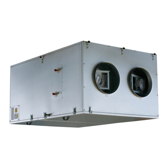
Page 4: Design
KOMFORT EC DW www.blaubergventilatoren.de DESIGN The casing is made of double-skinned aluzinc panels, internally filled Cold intake air passes by the heat exchanger and is warmed up to set with mineral wool layer 20 or 25 mm for heat- and sound-insulation. The temperature in the heater. -
Page 5: Operating Logic
KOMFORT EC DW www.blaubergventilatoren.de For mounting facilitation the KOMFORT EC DW600-2/1000-4 unit is available both in left- and right-handed modifications. RIGHT-HANDED MODIFICATION LEFT-HANDED MODIFICATION (TOP VIEW) (TOP VIEW) Fig. 2. KOMFORT EC DW600-2/DW1000-4 modifications OPERATING LOGIC Cold fresh air from outside flows through the heat exchanger and is air. -
Page 6: Technical Data
KOMFORT EC DW www.blaubergventilatoren.de TECHNICAL DATA Table 1. Technical data of the unit KOMFORT EC KOMFORT EC KOMFORT EC KOMFORT EC Parameters DW600-2 DW1000-4 DW2000-2 DW3800-2 Unit voltage [V /50-60 Hz] 1~ 230 3~ 400 Number of water heater rows Power [kW] 0,27 0,84... - Page 7 KOMFORT EC DW www.blaubergventilatoren.de How to use water heater diagrams Sample parameters: Air flow = 400 m /h. Outside air temperature =-20°C. Water temperature (in/out) = 70/50 °C. Supply air temperature: prolong the line of air flow (e.g. 400 m up to the point where it crosses the outside air temperature (blue curve, e.g.
- Page 8 KOMFORT EC DW www.blaubergventilatoren.de How to use water heater diagrams Sample parameters: Air flow = 1450 m /h. Outside air temperature =-25°C. Water temperature (in/out) = 70/50 °C. Air Speed inside coil: Starting from 1450 m /h on the air flow scale draw a vertical line .
-
Page 9: Mounting
KOMFORT EC DW www.blaubergventilatoren.de MOUNTING WARNING Safety precautions: The unit must be mounted to a rigid and stable structure. The unit must be suspended using anchor bolts. Before starting mounting check that the mounting structure has sufficient loading capacity for the unit weight. The unit mounting is allowed only after power cut-off and full stop of the rotating parts. - Page 10 KOMFORT EC DW www.blaubergventilatoren.de The unit is suspended using threaded rods and threaded dowels. In case of insufficient length or no air ducts cover the unit spigots with a The unit must be mounted to an even surface to avoid the unit casing protecting grille or any other protecting device with maximum mesh width distortion and operation disturbances.
-
Page 11: Condensate Drainage
KOMFORT EC DW www.blaubergventilatoren.de Connection diagram for the water heater mixing unit (to be ordered separately) is shown in Fig. 12. Regulating heat medium valve actuator Water mixing unit connection diagram 1. Water heater. 6. Heat medium regulating valve with an actuator. 2. -
Page 12: Connection To Power Mains
KOMFORT EC DW www.blaubergventilatoren.de CONNECTION TO POWER MAINS WARNING Read the service instruction prior to any electric installations. Connection of the unit to power mains is allowed by a qualified electrician only. The rated electrical parameters are stated on the rating plate. No modifications of internal connections are allowed and will result in void warranty. - Page 13 KOMFORT EC DW www.blaubergventilatoren.de Outside Indoor SM2 SM1 12 V AC Power supply 230 V AC 24 V AC Digital input (DI) Digital output (DO) Analogue input (AI) Analogue output (AO) RS485 Symbol Name Symbol Name Supply air damper SM2* Exhaust air damper actuator Exhaust air damper Bypass air damper actuator...
- Page 14 KOMFORT EC DW www.blaubergventilatoren.de N PE 1 21 22 23 nc c +12V Gnd Out N PE +12V Gnd Gnd Out — ELECTRIC SHOCK HAZARD! 1. The unit includes only P1 and TE1 items. 2. ** The maximum connecting cable length is 20 m! Sign Name Type...
-
Page 15: Outdoor Temperature Sensor Mounting And Connection
KOMFORT EC DW www.blaubergventilatoren.de OUTDOOR TEMPERATURE SENSOR MOUNTING AND CONNECTION The unit is supplied with an outdoor temperature sensor. subjected to direct solar light. The outdoor temperature sensor mounting is as follows, Fig. 18: 4. Install the sensor cover back. 1. -
Page 16: Control Panel Mounting
KOMFORT EC DW www.blaubergventilatoren.de CONTROL PANEL MOUNTING The units have an integrated control system with a wall-mounted control for connection of the unit and the control panel. The control panel technical panel with a sensor display. The standard delivery set includes a 10 m cable data are shown in Table 4. - Page 17 KOMFORT EC DW www.blaubergventilatoren.de Recommended cable length from the wall surface is 90 mm Fig. 21. Control panel mounting The control panel includes a lithium cell CR1220 with a limited time 3. Open the top of the casing to allow access to the upper circuit board. resource.
-
Page 18: Unit Control
KOMFORT EC DW www.blaubergventilatoren.de UNIT CONTROL General description of the automatic control system. The unit is controlled from the wall-mounted control panel with a sensor display, Fig. 22. Fig. 22. Control panel Table 6. Operation and parameter setup of the unit Function Indication Main Menu... - Page 19 KOMFORT EC DW www.blaubergventilatoren.de Table 6. Operation and parameter setup of the unit (continued) Function Indication Fan Speed Changeover Fan speed setting: Press the AIR FLOW button The unit has four speed stages: - Speed 1; - Speed 2; - Speed 3;...
- Page 20 KOMFORT EC DW www.blaubergventilatoren.de Table 6. Operation and parameter setup of the unit (continued) Function Indication User Menu To enter the User menu press MENU in the Main menu. The User menu contains basic menu items and functions for parameters setting: ENG.
- Page 21 KOMFORT EC DW www.blaubergventilatoren.de Table 6. Operation and parameter setup of the unit (continued) Function Indication For navigating in the Engineering menu use the following buttons: - moving upwards in the list. - moving downwards in the list. - elect the value from the parameter list. - return to the User menu.
- Page 22 KOMFORT EC DW www.blaubergventilatoren.de Table 6. Operation and parameter setup of the unit (continued) Function Indication Language Selection To select the control panel interface language select the LANGUAGE submenu from the Engineering menu and press ENTER Select the desired language from the list. ...
- Page 23 KOMFORT EC DW www.blaubergventilatoren.de Table 6. Operation and parameter setup of the unit (continued) Function Indication 12 Standby Mode Settings Select the STANDBY MODE item in the Engineering menu and press ENTER Use the buttons to select 0 or 1 in the AIR FLOW window: •...
- Page 24 KOMFORT EC DW www.blaubergventilatoren.de Table 6. Operation and parameter setup of the unit (continued) Function Indication 16 Control Panel Temperature Sensor Correction To correct the panel temperature sensor indications select TEMPERATURE CORRECTION submenu from the Engineering menu and press ENTER ...
- Page 25 KOMFORT EC DW www.blaubergventilatoren.de Table 6. Operation and parameter setup of the unit (continued) Function Indication To set up the AUTO mode press the button to enter the User menu and press AUTO ADJUST. While the TIMER is active the AUTO mode is disabled due to a lower priority.
- Page 26 KOMFORT EC DW www.blaubergventilatoren.de Table 6. Operation and parameter setup of the unit (continued) Function Indication 21 Motor Hours The MOTOR HOURS function enables the user to set up filter cleaning or replacement periodicity. Upon expiration of the pre-set time the panel displays a filter cleaning or replacement indicator.
-
Page 27: Error Code Description
KOMFORT EC DW www.blaubergventilatoren.de ERROR CODE DESCRIPTION Table 7. Error code description Error code Description Outdoor temperature sensor malfunction. Malfunction of the temperature sensor for heat exchanger freezing protection. Return heat medium temperature sensor malfunction. Water heater freeze protection sensor malfunction. Duct temperature sensor malfunction. -
Page 28: Technical Maintenance
KOMFORT EC DW www.blaubergventilatoren.de TECHNICAL MAINTENANCE WARNING! Cut power supply to the unit off by turning the automatic electric switch QF to OFF position prior to any maintenance operations. Take steps to prevent re-activation of the automatic switch. Regular technical supervision and maintenance of the unit are required to Warning! Consider the unit sharp edges! Fulfil maintenance ensure the product long service life and non-stop operation. -
Page 29: Troubleshooting And Fault Handling
KOMFORT EC DW www.blaubergventilatoren.de 4. Condensate drain system maintenance (once per year). 6. Air ducts maintenance (once in 5 years). Extract air particles may accumulate in the condensate drain system and The regular unit maintenance in compliance with the above rules may cause its clogging. -
Page 30: Acceptance Certificate
Company: Name Date Signature WARRANTY CARD KOMFORT EC DW600-2 KOMFORT EC DW2000-2 KOMFORT EC DW1000-4 KOMFORT EC DW3800-2 SELLER SALES DATE REPRESENTATIVE IN EU BLAUBERG Ventilatoren GmbH Aidenbachstr. 52a, D-81379 Munich, Germany KOMFORT EC DW v1(6)_EN.indd 30 10.08.2015 10:11:18... - Page 31 KOMFORT EC DW www.blaubergventilatoren.de KOMFORT EC DW v1(6)_EN.indd 31 10.08.2015 10:11:18...
- Page 32 www.blaubergventilatoren.de KOMFORT EC DW v.1(6) / EN KOMFORT EC DW v1(6)_EN.indd 32 10.08.2015 10:11:18...
Need help?
Do you have a question about the KOMFORT EC DW Series and is the answer not in the manual?
Questions and answers