Advertisement
Quick Links
Advertisement

Related Manuals for phase II 900-345


Summary of Contents for phase II 900-345
- Page 1 Superficial Rockwell Hardness Testers Model No. 900‐345 Analog Superficial Rockwell Hardness Tester Model No. 900‐345D Superficial Rockwell Hardness Tester w/Digital Indicator Operation Manual 21 Industrial Ave Upper Saddle River, NJ. 07458 (201) 962‐7373 www.phase2plus.com Page 1...
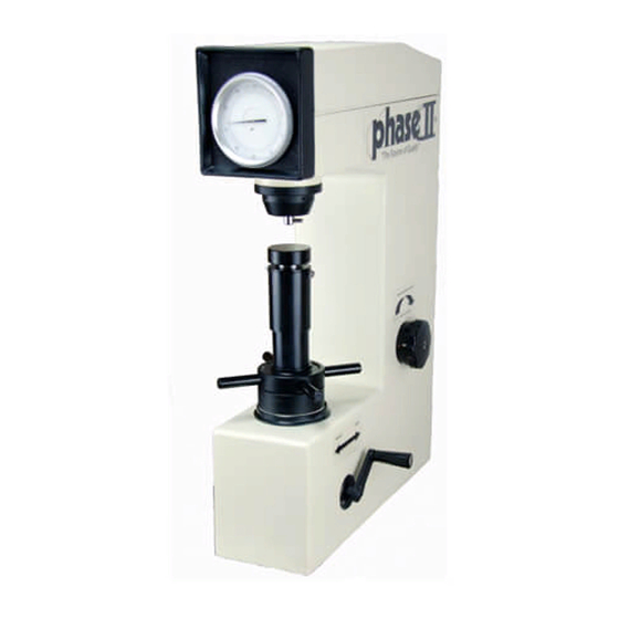
- Page 2 Superficial Rockwell Hardness Testers MODEL NO. 900‐345D To reference digital indicator functions and usage, please see 900345-9500 Operation Manual at the back of this manual Operating Instructions & Parts Manual Please read and save these instructions. Read carefully before attempting to assemble, install, operate or maintain the products described. Protect yourself and others by observing all safety information. Failure to comply with instructions could result in personal injury and/or property damage! Retain Instructions for future reference. Description The 900‐345 Hardness Tester accurately measures hardness of materials in Rockwell N and T scales. Heat‐treated steels are tested using a 120 diamond indentor in the N‐scale. Soft/thin materials are tested using a 1/16" carbide ball indentor in the T‐scale. This tester features a weight adjustment knob for quick and easy adjustments between different scales. Release/reset lever is provided for quick and accurate testing. Hardness Tester includes standard, large and V‐shaped anvils for holding small, large and round or curved materials. Storage box, test blocks, 120 diamond indentor and a 1/16”carbide ball indentor. Unpacking Tool Kit: A. Large Anvil B. V‐shaped Anvil C.
- Page 3 Operating Instructions & Parts Manual General Safety Instructions 1. Never use clamps, straps, any other tooling or equipment to mount specimen to the tester anvil. 2. Always use the proper anvil supplied. 3. Be sure to use proper indentor and weight for material and hardness to be tested. (See Figure 3). Hardness Tester Should Be Properly Maintained 1. Consult operation instructions for specific maintainance and adjusting procedures. 2. Keep the machine clean for best results. 3. Remove adjusting tools and wrenches from work space. 4. Keep all parts in working order. Check to determine that the parts will operate properly and perform their intended function. 5. Check for damaged parts. Check for alignment, binding, breakage, mounting and any other condition that may affect tool's operation. 6. Part that is damaged should be properly repaired or replaced. Do not perform makeshift repairs. (Use the parts list provided to order replacement parts.) Basic Set‐Up Information: 1) Remove Top crate cover from base. Carefully lift straight up to avoid scratching the side of the machine 2) Remove the tool kit and manual from the base of the crate 3) Remove plastic machine cover 4) With assistance, remove the two bolts under the base of the crate to remove the machine from the base. 5) Place machine on a sturdy vibration free table or bench. Bench should be rated for up to 500lbs. 6) It is recommended that the machine gets mounted to a sturdy bench as shown below. 7) Optional Bench/Cabinet Model No. 900331‐STAND 8) In order for leadscrew to be lowered to accept maximum size part, you must drill a hole in the table to allow leadscrew to travel through. This procedure is not necessary if using our cabinet stand as shown above.
- Page 4 Operating Instructions & Parts Manual Example of weights hung on support bar Weight #1 Weight #2 Weight#3 Rockwell B Indentor Rockwell C Indentor 1/16” Carbide Ball Diamond Page 4...
- Page 5 Operating Instructions & Parts Manual Adding Oil to the Dashpot If when moving the Load/Unload handle and you feel it make fast hard contact or hear a suction noise then its time to check the dashpot. On the left side of the machine (when standing in front of it) there is a small metal access plate held on by 2 small screws. Remove the screws and plate to expose the valve and reservoir. Push the Load/Unload handle towards the back of the machine. Remove the screw #25 and carefully add high grade hydraulic oil into the hole. Begin pulling/pushing the Load/Unload handle back and forth until any suction noise has disappeared. Replace screw #25. Replace access plate. Dashpot Adjuster/Filler Page 5...
- Page 6 Operating Instructions & Parts Manual Seating Your Diamond: Caution: To ensure accuracy, mount the indentor by sliding it in the holder as far as possible and then securing the indentor by tightening the set screw finger‐tight only. Place HRC test block on the small round anvil and begin by turning the handwheel clockwise until the block just touches the diamond. At this point, continue rotating the handwheel until the large needle goes around approx. 3 revolutions. Let the machine sit idle for a few seconds and then loosen the set screw. Wait a few more seconds and then tighten the set screw back up. This will allow the diamond to be “seated” in the shank. Take the load off by turning the handwheel counter‐clockwise and you can begin following instructions below. Rotate the weight adjustment knob until the required weight scale is aligned with the alignment mark on the frame of the machine. 1. Prepare the test specimen properly. Be sure that the top and bottom surfaces of the specimen are clean and free of any grease, oil dirt, etc and free of any burrs or debris. 2. For small specimens (under 3" maximum length or diameter) use the small round anvil. Use the large anvil for larger specimens. Use the V‐shaped anvil for round or curved specimens. Warning! Do not test any specimen that cannot be safely and properly positioned on and supported by the tester anvil Operation: Determine the proper indentor, scale and weight for the material hardness to be tested (see Figure 3). Mount the required indentor in the indentor holder using the set screw (Fig. 6, Ref. Nos. 27 and 28) on the side of the holder. Test Procedure Test procedure consists of a preload of the specimen using the force of the elevation screw and a test load using the weights and lever arm assembly. Be sure that the weight reset handle is in rest (“unload”) position. 1. Mount specimen on required anvil. Rotate the elevation screw threaded collar clockwise slowly until the specimen contacts the indentor. Be sure to position specimen so the indentor contacts clean, untested material. 2. Preload the specimen by rotating the leadscrew collar slowly until the large needle on the dial indicator rotates two to three (2‐3) revolutions. Stop rotation of handwheel when the large needle is within 3 hash marks of vertical(TDC) Caution: As the large needle is properly rotated 2‐3 revolutions, the small needle rotates counterclockwise 90 to vertical at the red dot. If the large needle overshoots vertical by more than 5 hash marks, the test is invalid and must be repeated from step 1. 3.
- Page 7 Operating Instructions & Parts Manual Fine Adjustment: Set Screw Hex Nut Adjuster Knob Back side of indicator Please be sure to make very slight adjustments when calibrating the 900‐345A as this machine is extremely sensitive to any movement. Remove the top cover off the 900‐345A. Adjusting the set screw that controls the Indicator needle starting point: Carefully hold the set screw with a thin blade regular screwdriver. While holding this screw steady, carefully loosen the set screw hex nut. Making a very slight turn Counter‐Clockwise on the set screw, you will see the large needle on the dial begin to turn counter‐clockwise on the dial. Continue turning until there is no more contact between the set screw and needle adjuster. At that point turn the set screw until it just touches the adjuster and snug the hex nut back in place while holding the set screw to prevent it from turning. Take a minimum of 3 tests on your test block to make sure the machine is reading correctly. If readings are low, you will need to back off on the set screw a little more. The opposite if readings are high. Page 7...
- Page 8 Operating Instructions & Parts Manual Maintenance 1. If large needle on the dial indicator rotates suddenly at first and then slows during a test, then the dash pot may be low on oil. To fill the dash pot, go to Page 5 in this manual and follow instructions. Bleed the air from the dash pot by manually raising and lowering the dash pot piston until all air bubbles have been released from under the piston. 2. Be sure elevation screw and threaded collar are clean and lubricated. Lubricate with general purpose wheel bearing grease. 3. Keep top of leadscrew, collar and anvils clean and free of grease, oil, dirt, burrs, etc. 4. Use the test blocks periodically to check tester accuracy. Troubleshooting Chart Symptom Possible cause(s) Corrective Action Incorrect hardness measurement 1. Contaminants effecting 1. Be sure the anvil, top of elevation measurement screw, threaded collar, indentor and specimen are all clean and free of oil, grease, dirt, shavings, debris, etc. 2. Be sure elevation screw cover and top is clean and free of any 2. Elevation screw cover & top, are dirt, oil, grease, etc. Position interfering with specimen, anvil cover properly on the elevation or elevation screw.
- Page 9 Operating Instructions & Parts Manual ASTM Hardness Conversion Chart Rockwell C Hardness Range Approximate Hardness Conversion Numbers for Non-Austenitic Steels, According to ASTM E-140 The Conversion Values contained herein should be considered approximate only and may be inaccurate for specific applications Vickers Knoop Brinell...
- Page 10 Operating Instructions & Parts Manual ASTM Hardness Conversion Chart Rockwell B Hardness Range Approximate Hardness Conversion Numbers for Non-Austenitic Steels, according to ASTM E-140.The conversion values contained herein should be considered approximate only and may be inaccurate for specific applications. Rockwell Superficial Rockwell Vickers...
- Page 11 Operating Instructions & Parts Manual 34.6 86.5 76.6 49.0 21.7 34.1 85.5 76.2 48.3 20.7 33.7 75.9 47.7 19.7 33.3 84.6 76.6 47.0 18.7 32.9 76.3 46.3 17.7 32.4 83.5 74.9 45.7 16.7 32.0 82.5 74.6 45.0 15.7 31.6 74.3 44.3 14.7 31.2...
- Page 12 Operating Instructions & Parts Manual ASTM Hardness Minimum Thickness Requirements Minimum allowable thickness for a corresponding hardness in the respective scales Minimum Minimum Rockwell Rockwell Rockwell Superficial Superficial Superficial Superficial Superficial Superficial Thickness Thickness 15N 30N 45N 15T 30T 45T Inch 0.006 0.15 … … … … … … … … … 0.008 0.20 …...
- Page 13 Operating Instructions & Parts Manual Rockwell Hardness: Scale/Indentor/Load Chart Scale Indentor Type Preliminary Total Typical Applications Symbol Force Force N (kgf) N (kgf) Spheroconical 98.07 (10) 588.4 (60) Cemented carbides, thin steel, and shallow case hardened steel Diamond 1/16” Carbide Ball 98.07 (10) 980.7 (100) Copper alloys, soft steels, aluminum alloys, malleable iron, etc. Spheroconical 98.07 (10) 1471 (150) Steel, hard cast irons, pearlitic malleable iron, titanium, deep case Diamond hardened steel, other harder than HRB 100 Spheroconical 98.07 (10) 980.7 (100) Thin steel and medium case hardened steel, and pearlitic Diamond malleable iron 1/8” Carbide Ball...
- Page 14 Operating Instructions & Parts Manual 1. Load/Unload Handle 2. Turn wheel 3. Lifting Screw Cover 4. Anvil 5. Indenter 6.Screws 7. Top cover 8. Screws 9. Rear cover 10. Indicator 11. Indenter Locking Screw 12. Weight Load Handwheel Page 14...
- Page 15 Operating Instructions & Parts Manual Main Headquarters: U.S.A Phase II Machine & Tool, Inc. 21 Industrial Ave Upper Saddle River, NJ. 07458 USA Tel: (201) 962‐7373 Fax: (201) 962‐8353 General E‐Mail: info@phase2plus.com BEIJING, CHINA Phase II Measuring Instruments (Beijing) Ltd. Room 301, Bldg 2 Qing Yuan Xi Li, Haidian District, Beijing 100192,China Tel:+86‐10‐59792409 Fax:+86‐10‐59814851 General E‐mail: info@phase2china.com.cn MEXICO Phase II de Mexico Calle A No. 4 Promer Piso Col. San Marcos Azcapotzalco C.P 02020 Mexico Tel: 011‐525‐5538‐39771 Fax: same General E‐mail: phase2mexico@hotmail.com VENEZUELA Phase II Herramientas Universales EDCM. CA. Av. Francisco Lazo Marti CC Plaza Santa Monica PB Local Santa Monica, Caracas 1040 Venezuela Tel: 212‐690‐28‐21 Fax: 212‐693‐29‐16 E‐mail: edcphm@movistar.net Page 15...
-
Page 16: Digital Indicator
Operating Instructions & Parts Manual Digital Indicator Series 9500 Digital Indicators www.phase2plus.com Page 16... - Page 17 Operating Instructions & Parts Manual IMPORTANT! Follow the instructions for setting up the indicator BEFORE performing any tests. Once the indicator is set up you can begin taking tests as shown in the manual on Page 10. Features: The 9500 series digital indicators are an accurate yet affordable option to replace the dial on your analog hardness tester. The 9500 series indicator gives you the complete functionality of a true digital machine with popular features such as statistics, memory, conversions to Brinell or Vickers, limit setting and more. Each indicator will come complete with Data Cable and Charger with cable. External Structure: Menu/ Charger Enter Port Charger plug Down Power Lock/ “ZERO” Exit LCD Display: Page 17...
-
Page 18: Specifications
Operating Instructions & Parts Manual Specifications: Model No. 900331‐9500/900330‐9500 900345‐9500 Scales‐Rockwell A, B, C, D, E, F, G, H, K 15N, 30N, 45N, 15T, 30T, 45T Resolution 0.1HR 0.1HR Display 128x64 Matrix LCD 128x64 Matrix LCD w/Backlight w/Backlight Memory 1000 Readings 1000 Readings Conversions Brinell, Vickers Brinell, Vickers Power Ni‐Mh Battery w/Charger Ni‐Mh Battery w/Charger Auto‐Power Off Dimensions 114 x 37mm Dia. 114 x 37mm Dia. Mounting: 108x16mm Dia. Mounting: 108x16mm Dia. Weight 14.8oz. 14.8oz. Installation: 1) Be sure that indicator has sufficient charge. If the battery symbol is empty you should charge the indicator for approx. 1.5 hours prior to use. -
Page 19: Operation
Operating Instructions & Parts Manual Operation: 1) Power the indicator on. 2) There will be a value shown on the display. This value must be set to ZERO by turning the fine adjustment on your hardness tester as shown in the picture below. Fine Adjustment Set Screw Example of display at Zero point. Page 19... - Page 20 Operating Instructions & Parts Manual Setting Parameters: 1) Hardness Scale: Press the Menu/Enter button. Make sure Measurement is highlighted. Press the Menu/Enter button again and SCALE should be highlighted. Press the Menu/Enter button to open up the list of hardness scales. Use the Arrow buttons to scroll through the choices and highlight the scale that you want the indicator to read in. If you are not sure about your selection, please reference the chart below: Auto Locking: This feature will automatically hold the hardness value the moment the reading is stable. On softer metals the penetrator may continue to indent the material which may affect the reading. The lock feature will prevent the value from changing once stabilized even though the penetrator may still be moving. Auto Locking con’t: If you don’t want this feature then turn it off by changing in the menu. Follow instructions below: 1) Press the Menu/Enter button. Make sure Measurement is highlighted. Press the Menu/Enter button again and scroll down to Auto Locking. Auto‐Locking should be highlighted. Press the Menu/Enter button to open up the choices. Use the Arrow buttons to scroll through the choices and highlight OFF if you don’t want to use this feature. Page 20...
- Page 21 Operating Instructions & Parts Manual Auto Zero: This feature should be left on for normal operation! The 9500 series indicators allow you to select either Auto Zero or you can manually set zero. Auto zero will bring the value back to zero automatically after the load is removed from the previous test. When the indicator is set to Manual Zero you may need to pres the Zero button on the indicator to be sure its set to Zero before the next test is performed. Follow instructions below: 1) Press the Menu/Enter button. Make sure Measurement is highlighted. Press the Menu/Enter button again and scroll down to Auto Zero . Highlight Auto Zero. Press the Menu/Enter button to open up the choices. Use the Arrow buttons to scroll through the choices and highlight OFF if you don’t want to use this feature. Statistics: This feature allows you to set the number of tests to be averaged. The results will automatically be shown on the display after each test. Once the set number of tests have been obtained, the average and repeatability value will be shown on the display. Statistics, con’t: 1) Press the Menu/Enter button. Make sure Measurement is highlighted. Press the Menu/Enter button again and scroll down to Statis Points. Statis Points should be highlighted. Press the Menu/Enter button to open up the choices. Use the Arrow buttons to scroll through the values of 2 Thru 9. According to ASTM, you should take a minimum of 5 tests and obtain your average for the true hardness value of your part. If you don’t want to use this feature then scroll down past “2” and the display will show “OFF”. Conversions: The 9500 series indicators will display conversions to either Brinell or Vickers scale once this feature is turned on. 1) Press the Menu/Enter button. Make sure Measurement is highlighted. Press the Menu/Enter button again and scroll down to Conversions. Conversions should be highlighted. Press the Menu/Enter button to open up the choices. Use the Arrow buttons to scroll through the choices and highlight OFF if you don’t want this feature. Page 21...
- Page 22 Operating Instructions & Parts Manual Upper/Lower Limit Setting: The 9500 series indicators have an Upper/Lower limit setting with alarm. Once set, the indicator will alert you to a hardness value that is outside of your preset limits. See instructions for limit setting below: 1) Press the Menu/Enter button. Make sure Measurement is highlighted. Press the Menu/Enter button again and scroll down to Limit Alarm. Limit Alarm should be highlighted. Press the Menu/Enter button to open up the choices. Use the Arrow buttons to scroll through the choices and highlight OFF if you don’t want this feature. Highlight Enter and press the Menu/Enter button to set your limits. Use the Up and Down arrows to change the values to match your desired limit settings. Once obtained, press the Menu/Enter button to save. Scroll up to ON and highlight that. Press the Menu/Enter button to save and return to the main test screen. Memory Functions: The 9500 series indicators can store up to 999 hardness values and can be viewed at your convenience by accessing the memory. Access the memory setting by following below: 1) Press the Menu/Enter button. Scroll down to Memory and highlight it. Press the Menu/Enter button again and you will see the three choices available for this indicator. Browse All: This allows you to view all of the values stored in the memory. Browse Select: This allows you to select the values in memory by a particular hardness scale. In other words, if you only want to see the Rockwell C scale values, you would select HRC in this menu. Print: This is not an option on the 9500 series indicators. System Settings: 1) Key Tone: This feature can be turned on or off in the menu. 2) Backlight: This feature can be turned on or off in the menu. 3) Language: This indicator can be set to English or Chinese in the menu. 4) Date/Time Setting: You can set the date and time in the menu. Page 22...
-
Page 23: Taking A Test
Operating Instructions & Parts Manual TAKING A TEST: Assuming the indicator has been set up correctly and the Auto Zero is turned on, you can begin taking a test as you normally would with your hardness tester. A) Make sure you have the correct penetrator installed and the weight selection set for your hardness scale. Reference the Weight Load Indentor Chart 1) Be sure that your anvil is clean of oil, dust, rust, etc. 2) Place a good quality calibration test block on the anvil and begin rotating the test block up until you just make contact with the penetrator. 3) Continue rotating up and immediately take not of the Analog bar on the left side of the indicator. This will rise as the block continues into the penetrator. The indicator will soon “Beep” alerting you that its almost at the top. Once the pre‐load is set the indicator will show either 2.80mm or 3.20mm (depending upon the scale set) and immediately change over to 100.0HRC. The analog bar will be solid right up to the Circle. See picture below: Pre-load Indicator 4) Once you see the display as shown above you must now apply the major load on the hardness tester. You will now see the values on the display change in a descending order. 5) Once the value on the display is stable (should be between 5‐8 seconds) you must now Unload the machine and you can take your reading directly off the indicator display. IMPORTANT! Your first test should always be discarded. Begin testing for average on the second test. ASTM suggests that you take 5 tests and obtain your average. That average is the value to be used as the true hardness reading. Page 23... - Page 24 Operating Instructions & Parts Manual CALIBRATION: The 9500 series indicators have a built‐in calibration feature which should only be used for fine adjustments. If the obtained results on your calibration blocks are well outside of tolerance, you should adjust and repair the base machine before you adjust the indicator. 1) Press the Menu/Enter button. Scroll down to System and highlight it. Press the Menu/Enter button again and you must scroll down to Correction. 2) Press the menu/Enter button and you will see three choices: a) Off b) On c) Enter If you don’t want to change calibration then leave it in the off position and return to the main test screen. If you highlight ON, this will activate the Auto‐Calibration feature which will allow the indicator to automatically correct the measured value when the “Lock” feature is on. If you highlight Enter, this will allow you to set the calibration by manually entering in the value shown on the test block. Example: If the value shown on your test block is HRC 25.8 then you would enter that value while in the enter screen. Now take a test on that same test block as normal. Once the result has been obtained Press the Menu/Enter button and then choose Save and then save the calibration. If you choose Exit then the calibration will not be saved. Maintenance: The 9500 series indicators are highly sensitive and accurate instruments and should be treated as such. These should remain in a temperature controlled environment with the least amount of shock or vibration as possible. Cleaning: Use soft damp cloth only. Do not use harsh chemicals as this will deteriorate the finish of the indicator. Technical Support and Repair: Contact Phase II at (201) 962‐7373 Page 24...
- Page 25 Operating Instructions & Parts Manual Effective: 12/1/2011 Warranty Policy: All portable and stationary material testing instruments manufactured for/by Phase II shall be free from defects in material and workmanship for a period of 1to 5 full years(depending upon model)from date of purchase. Parts found to be defective shall be replaced or repaired at Phase II’s sole discretion. Products found by Phase II to be misused, abused or neglected are not covered under this warranty. Parts not covered by this warranty are normal wear and consumable items such as (but not limited to) impact balls, impact bodies, diamond indentors, carbide ball indentors, impact springs, cables and connectors, batteries, diamond stylus, contact probes, etc. Consumable(wearable) items such as cables and probes have a 90 day warranty from date of purchase. This warranty is exclusive and in lieu of all other warranties whether written, oral or implied, including any implied warranties or merchantability or fitness for a particular purpose. In no event shall Phase II be liable for any incidental, special or consequential damages of any nature. Return Policy: All Phase II products must have authorization prior to return. If product is not acceptable for any reason including application issues and demonstrations, authorization for return must be obtained within 10 days of receipt of product. Unit must be in same new condition it was received. Failure to do so will result in an automatic 15% restocking fee. Returns after 30 days will not be accepted. Page 25...
Need help?
Do you have a question about the 900-345 and is the answer not in the manual?
Questions and answers