Sign In
Upload
Download
Table of Contents
Contents
Add to my manuals
Delete from my manuals
Share
URL of this page:
HTML Link:
Bookmark this page
Add
Manual will be automatically added to "My Manuals"
Print this page
×
Bookmark added
×
Added to my manuals
Manuals
Brands
Van Norman Manuals
Grinder
FG5000
Instruction manual and parts list
Van Norman FG5000 Instruction Manual And Parts List
Flywheel grinder
Hide thumbs
1
2
3
4
5
6
7
8
9
10
11
12
13
14
15
16
17
18
19
20
21
22
23
24
25
26
27
28
29
30
31
32
33
34
35
36
37
38
39
40
41
42
43
44
45
46
47
48
49
50
51
52
53
54
55
56
57
58
59
60
61
62
63
64
65
66
67
68
69
70
71
72
73
74
75
76
77
78
79
80
81
82
Table Of Contents
83
page
of
83
Go
/
83
Contents
Table of Contents
Bookmarks
Table of Contents
Warranty
Receiving Shipment
Important Note
Safety Information
Safety First
Safety Instructions
Electrical Requirements
Specifications
Standard Equipment
Optional Equipment
Grinding Wheels
Vw/Universal Flywheel Kit
Selecting Flywheel Grinding Stones
Product View and Parts Identification
Machine Description
Machine Set-Up
Fill Oil Reservoir
Fill Coolant Tank
Wire Machine
Rotation Checks
Operation
Wheel Dresser
Setting up Flywheel
Grinding Flywheel
Surface Finish
Recessed Flywheels
Radius Cutter Operation
Lubrication
Grinding Motor
Table Drive Gear Reduction Box
Machine Maintenance
Grinding Head Adjustments
Coolant Tank Removal and Cleaning
Side-To-Side Head Tilt Adjustment
Grinding Head Mounting
Head Lock Handle Position Adjustment
Leadscrew Backlash Adjustment
Column Side-To-Side Movement Adjustment
Assembly Drawing
Parts List
Switch Panel Assembly Diagrams
Control Box Assembly Diagrams
Wiring Diagrams
Advertisement
Quick Links
1
Machine Set-Up
2
Fill Oil Reservoir
3
Machine Maintenance
4
Assembly Drawing
5
Parts List
Download this manual
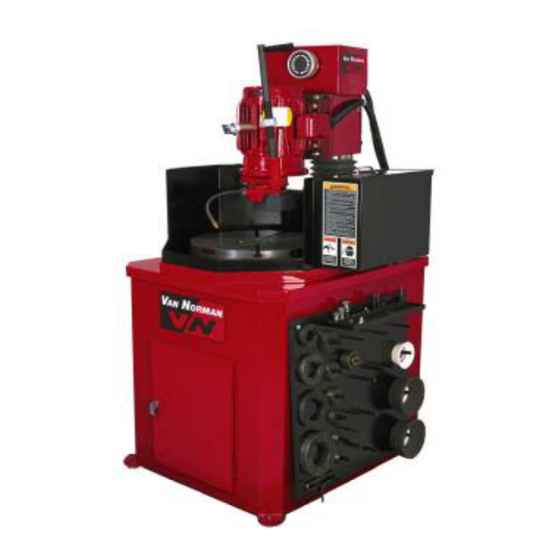
FG5000/10000
Flywheel
Grinder
Instruction Manual and Parts List
Van Norman
Copyright 2005 All Rights Reserved.
Equipment specifications, options and accessories subject to change without notice.
th
500 57
St., Marion, IA 52302
888-855-1789
319-377-9101 (FAX)
Table of
Contents
Previous
Page
Next
Page
1
2
3
4
5
Advertisement
Table of Contents
Need help?
Do you have a question about the FG5000 and is the answer not in the manual?
Ask a question
Questions and answers
Related Manuals for Van Norman FG5000
Grinder Van Norman FG10000 Instruction Manual And Parts List
Flywheel grinder (83 pages)
This manual is also suitable for:
Fg10000
Table of Contents
Save PDF
Print
Rename the bookmark
Delete bookmark?
Delete from my manuals?
Login
Sign In
OR
Sign in with Facebook
Sign in with Google
Upload manual
Upload from disk
Upload from URL


Need help?
Do you have a question about the FG5000 and is the answer not in the manual?
Questions and answers