Table of Contents
Advertisement
Quick Links
Advertisement
Table of Contents

Related Manuals for National Instruments SCC-68


Summary of Contents for National Instruments SCC-68
- Page 1 Artisan Technology Group is your source for quality new and certified-used/pre-owned equipment SERVICE CENTER REPAIRS WE BUY USED EQUIPMENT • FAST SHIPPING AND DELIVERY Experienced engineers and technicians on staff Sell your excess, underutilized, and idle used equipment at our full-service, in-house repair center We also offer credit for buy-backs and trade-ins •...
-
Page 2: Table Of Contents
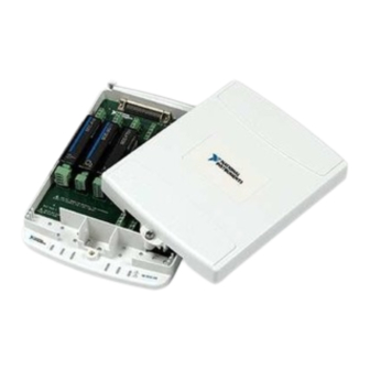
SCC-68 I/O Connector Block with 4 SCC Signal Conditioning Slots for DAQ Devices The SCC-68 is an I/O connector block for easy signal connection to a National Instruments M Series or E Series DAQ device. The SCC-68 features screw terminals and a general breadboard area for I/O signal connection, and bus terminals for external power and grounding. - Page 3 Bus Terminals...................15 Power Supply..................16 Using SCC Modules with the SCC-68 ............16 Supported SCC Modules ..............17 Connecting Signals to SCC Modules in the SCC-68 .......17 Power Supply Considerations............19 LED ...................20 Installing the SCC Modules in the SCC-68........21 SCC Connector Pinouts.............21 Direct Access to SCC signals............23 Analog Input Measurement Considerations ..........23...
-
Page 4: Conventions
This font is also used for the proper names of disk drives, paths, directories, programs, subprograms, subroutines, device names, functions, operations, variables, filenames, and extensions. SCC-XX This name refers to any SCC module. © National Instruments Corporation SCC-68 User Guide Artisan Technology Group - Quality Instrumentation ... Guaranteed | (888) 88-SOURCE | www.artisantg.com... -
Page 5: Using The Scc-68 Enclosure
To open the SCC-68, use a flathead screwdriver to loosen the captive screw at the front of the device. After the screw is loosened, pull up on the front of the enclosure cover to open. The top half of the SCC-68 enclosure can be removed completely. -
Page 6: Closing The Enclosure
Closing the Enclosure To close the SCC-68, align the two back tabs into the corresponding holes at the back of the base, as shown in the detail in Figure 2. With the cover and base of the enclosure aligned, snap the SCC-68 closed. To secure the SCC-68 enclosure, use a flathead screwdriver to push the screw down against the spring resistance and tighten the screw. -
Page 7: Stacking And Wall Mounting
SCC-68 connector blocks. Note The SCC-68 cannot be securely stacked onto another SCC-68 if the rear rubber feet are attached. The SCC-68 also has mounting holes on the bottom of the device for secure wall-mounting. -
Page 8: Installing Rubber Feet
Rubber non-skid feet are shipped with the device that can be attached for secure desktop use. To install the rubber feet, remove adhesive backing and affix to the SCC-68 where indicated in Figure 4. 1 Rubber Feet 3 Stacking Grooves 2 Wall-Mounting Holes Figure 4. -
Page 9: Connecting To The Daq Device
Connecting to the DAQ Device The following sections describe how to connect the SCC-68 to the DAQ device. The SCC-68 is designed to be used with M Series and E Series DAQ devices only. Other 68-pin devices may not function properly with the SCC-68. -
Page 10: Using The Scc-68 With A 68-Pin E Series Device
Attach the SCC-68 to Connector 0 of the DAQ device using one of the following cables: • SHC68-68-EPM • SHC68-68 • RC68-68 Proceed to the Taking Measurements with NI-DAQmx section for information about using the SCC-68 in measurement applications. To use the SCC-68 with a 32 AI channel M Series device using... -
Page 11: Using The Scc-68 With The Ni 6025E, Ni 6033E, Or Ni 6071E
Using the SCC-68 with the NI 6025E, NI 6033E, or NI 6071E To use the SCC-68 with the NI 6025E, NI 6033E, or NI 6071E, complete the following steps: Attach the SCC-68 to the DAQ device using an SH1006868 cable. This cable has two 68-pin connectors labeled MIO 16 and Extended I/O. -
Page 12: Scc-68 Features
SCC-68 Features The following sections describe the hardware features of the SCC-68. FOR PATENTS: NI.COM/PATENTS FRONT 4.75-5.25V 2A MAX Mod 1 Mod 2 Mod 3 Mod 4 USE SCC CONNECTOR BACKSHELL FOR HAZARDOUS LIVE SIGNALS (>42.4 Vpk / 60VDC) SCC-68... -
Page 13: Screw Terminals
By lacing the connector wires through these posts, movement is limited. Route all SCC signals through the left wire-entry side of the SCC-68. Route all other Note signals through the right wire-entry side. -
Page 14: Scc Modules
Breadboard Area The SCC-68 features a general breadboard area for custom circuitry such as filtering or attenuation. For soldering components to the underside of the breadboard, remove the printed circuit board by carefully snapping it loose from the SCC-68 enclosure. -
Page 15: Using The Temperature Sensor For Cold-Junction Compensation (Cjc)
Figure 8. SCC-68 Temperature Sensor Connection To use the temperature sensor for cold-junction compensation of thermocouple measurements, connect CJC+ (terminal 70) to AI channel 7 of the SCC-68. Figure 9 shows the temperature sensor connected to AI 7. CJC+ AI GND... -
Page 16: Cold Junction Temperature Measurement Accuracy
The bus terminals provide an easy interface for supplying external power, extra ground terminals, or grounding to any sensors or custom circuits used in the SCC-68. There are two buses—Bus A and Bus B—where all four screw terminals on each side are connected together internally. To use these... -
Page 17: Power Supply
I/O SCC modules. The SCC-68 is not compatible with analog output or counter SCC modules. Note If you use analog input SCC modules with the SCC-68, you must connect AI SENSE to AI GND, as shown in Figure 11. AI SENSE AI GND Figure 11. -
Page 18: Supported Scc Modules
Supported SCC Modules The SCC-68 supports all analog input and digital I/O SCC modules. Table 1 shows all SCC modules that are compatible with the SCC-68. Table 1. SCC-68-Compatible SCC Modules SCC Module Type SCC-AI0x Isolated Voltage Input SCC-TC0x Thermocouple Input... - Page 19 Figure 12. SCC Connector Backshell Refer to the SCC-XX user documentation for additional safety information. To connect an SCC module to the SCC-68, complete the following steps: Remove power from the signal lines. Strip insulation from the ends of the signal wires. Refer to the SCC-XX user documentation for the exact strip length for the module.
-
Page 20: Power Supply Considerations
You are using +5V to power custom circuitry on the breadboard area If the +5V power from the DAQ device drops below about 4.5 V, SCC modules installed in the SCC-68 will not operate properly. The LED in the SCC-68 will flash seven times per second to indicate this condition. There is no error or notification in software. -
Page 21: Led
SCC-68 Figure 14. SCC-68 Power Distribution Block Diagram The LED in the SCC-68 shows the status of the power supply. The SCC-68 monitors the voltage of the +5V signal from the DAQ device, as shown in Figure 14. Table 2 shows the correlation between power levels in the SCC-68 and the LED status. -
Page 22: Installing The Scc Modules In The Scc-68
Installing the SCC Modules in the SCC-68 To install the SCC modules on the SCC slots of the SCC-68, plug the SCC modules onto the appropriate connector block sockets. When properly oriented, SCC modules plug easily onto the connector block socket. Never force an SCC module onto the socket. - Page 23 SCC-68 User Guide ni.com Artisan Technology Group - Quality Instrumentation ... Guaranteed | (888) 88-SOURCE | www.artisantg.com...
-
Page 24: Direct Access To Scc Signals
If you are using SCC modules for some of the AI signals, you can also measure other AI signals using the AI screw terminals in the SCC-68. Refer to Figure 6 for the location of the AI screw terminals. -
Page 25: Differential
A single-ended connection is a connection in which the device AI signal is referenced to a ground that it can share with other input signals. National Instruments M Series and E Series devices provide two single-ended connection configurations. SCC-68 User Guide ni.com... -
Page 26: Non-Referenced Single Ended (Nrse)
SCC-68, the following cases should also be noted. Grounded Signal Sources If you have SCC modules installed in the SCC-68, differential measurements are recommended over NRSE measurements. When you have SCC modules installed, connect AI GND to AI SENSE. If you connect the ground of the signal source to AI SENSE, you are also shorting it to AI GND. -
Page 27: Floating Signal Sources
AI GND causes an error when measuring the signal. The amount of this error depends on several factors including the length of the cable connecting the DAQ device to the SCC-68 and the amount of current being drawn by the SCC-68 from the DAQ device +5V power supply. -
Page 28: Taking Measurements With Ni-Daqmx
If RSE is used to measure floating signals, there will be a measurement error due to the current being drawn by the SCC-68 from the DAQ device +5V power supply. This potential will vary depending on the length of the cable connecting the DAQ device to the SCC-68 and the amount of current being drawn from the +5V power supply by the SCC-68. -
Page 29: Configuring The Scc-68
Configuring the SCC-68 The SCC-68 can be configured as an SCC carrier and as a screw terminal accessory. To configure the SCC-68 as both an SCC carrier and a screw terminal accessory, you need to follow the configuration instructions in the Configuring the SCC-68 as an SCC Carrier section and the Configuring the SCC-68 as a Screw Terminal Accessory section. -
Page 30: Configuring Channels And Tasks
Configure a Task When using NI-DAQmx, configure tasks with the DAQ Assistant. To create tasks using the SCC-68, you must have NI-DAQmx version 8.1 or later. • To launch the DAQ Assistant in MAX, right-click Data Neighborhood and select Create New. - Page 31 The DAQ Assistant prompts you to create a new task. Select an I/O type, such as analog input. For thermocouple measurements, you must first ensure the hardware is configured correctly and that the SCC-68 has been configured in MAX. For more information, refer to the Configuring the SCC-68 section.
-
Page 32: Configure Global Virtual Channels
CJC sensor is wired to AI 7, then select Built-In for the CJC source. If this option is not available, check your configuration. For more information, refer to the Configuring the SCC-68 section. For CJC sensor wiring instructions, refer to the... -
Page 33: Using Your Task In An Application
LabWindows/CVI. Measurement Studio Refer to and enter the information code ni.com/info rddqms step-by-step instruction for using a task in Measurement Studio. SCC-68 User Guide ni.com Artisan Technology Group - Quality Instrumentation ... Guaranteed | (888) 88-SOURCE | www.artisantg.com... -
Page 34: Specifications
Typical ..........1 mA with no signal conditioning installed Note The maximum power consumption of the SCC-68 is a function of the SCC modules installed and any circuits constructed on the general-purpose breadboard area. Refer to the Power Supply Considerations section for more information. - Page 35 CJC voltage measurement For more information about the temperature sensor, refer to the Using the Temperature Sensor for Cold-Junction Compensation (CJC) section. SCC-68 User Guide ni.com Artisan Technology Group - Quality Instrumentation ... Guaranteed | (888) 88-SOURCE | www.artisantg.com...
- Page 36 17.78 cm (2.09 in.) (7.00 in.) 24.46 cm (9.63 in.) Figure 20. SCC-68 I/O Connector Block Dimensions Weight ............ 623.7 g (1 lb 6 oz) I/O connectors ........One 68-pin male SCSI connector SCC sockets Number of sockets ......4 SCC types supported.......
- Page 37 Maximum working voltage refers to the signal voltage plus the common-mode voltage. Channel-to-earth ........11 VDC, Measurement Category I Do not use the SCC-68 for connections to signals or for measurements within Caution Categories II, III, or IV. Environmental Operating temperature ......0 to 55 °C Storage temperature ........–20 to 70 °C...
- Page 38 Note Nonoperating random vibration profiles for the SCC-68 exceeds the requirements of MIL-PRF-28800F, Class 3. Safety This product is designed to meet the requirements of the following standards of safety for electrical equipment for measurement, control, and laboratory use: •...
-
Page 39: Quick Reference Guides
Connector 1 of 68-pin M Series devices, and E Series devices. The quick reference guides provide information about pin placements, their corresponding signal assignments, and wire-stripping length for signal connections. SCC-68 User Guide ni.com Artisan Technology Group - Quality Instrumentation ... Guaranteed | (888) 88-SOURCE | www.artisantg.com... - Page 40 © National Instruments Corporation SCC-68 User Guide Artisan Technology Group - Quality Instrumentation ... Guaranteed | (888) 88-SOURCE | www.artisantg.com...
- Page 41 SCC-68 User Guide ni.com Artisan Technology Group - Quality Instrumentation ... Guaranteed | (888) 88-SOURCE | www.artisantg.com...
- Page 42 © National Instruments Corporation SCC-68 User Guide Artisan Technology Group - Quality Instrumentation ... Guaranteed | (888) 88-SOURCE | www.artisantg.com...
- Page 43 Instruments trademarks. Other product and company names mentioned herein are trademarks or trade names of their respective companies. For patents covering National Instruments products, refer to the appropriate location: Help»Patents in your software, the patents.txt file on your CD, or ni.com/patents.
- Page 44 Artisan Technology Group is your source for quality new and certified-used/pre-owned equipment SERVICE CENTER REPAIRS WE BUY USED EQUIPMENT • FAST SHIPPING AND DELIVERY Experienced engineers and technicians on staff Sell your excess, underutilized, and idle used equipment at our full-service, in-house repair center We also offer credit for buy-backs and trade-ins •...
Need help?
Do you have a question about the SCC-68 and is the answer not in the manual?
Questions and answers