
Related Manuals for AMS AS5601


Summary of Contents for AMS AS5601
- Page 1 Operation Manual: AS5601-SO_RD_ST AS5601 12-bit Programmable Contactless Potentiometer www.ams.com Revision 1.0 / 30.06.2014 page 1/11...
-
Page 2: Table Of Contents
2.4.1 Incremental Mode ........................ 6 2.4.2 Pushbutton Detection ......................6 2.4.3 C Mode ..........................7 AS5601 Configuration ......................7 Programming the output range .................... 7 Programming a configuration ....................7 3.2.1 Low Power Mode ......................... 8 3.2.2 Hysteresis ..........................8 3.2.3... -
Page 3: General Description
The AS5601 reference design is a contactless rotary knob with 16 mechanical positions and a pushbutton detection. It can be programmed over I Note: The AS5601 is configured for a 16 positions grid and for the modules zero position. 2.1 Adapter Board Pin-Out... -
Page 4: Adapter Board Description
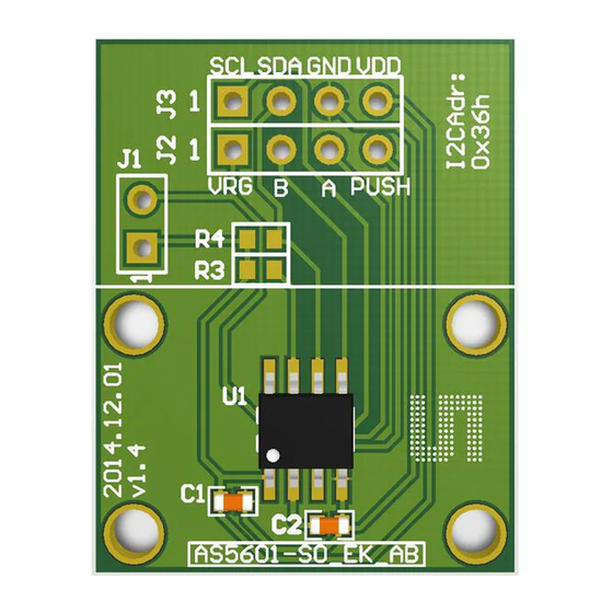
Incremental output B I2C Data I2C Clock Ground 2.2 Adapter Board Description The AS5601 is connected over the 7-way header. Connect the desired pins of the AS5601 using the headers and resistors. Figure 1: AS5601-SO_RD_ST PCB Description Short J1 to operate in 3.3V... - Page 5 AS5601-SO_RD_ST Operation Manual Figure 2: Module set-up The configuration of the reference module is shown in Figure Figure 3: Module Cross-Section Push Magnet Sensor Magnet AS5601 www.ams.com Revision 1.0 / 30.06.2014 page 5/11...
-
Page 6: Electrical Setup
The magnet is already aligned to get AGC values in the middle of the AGC range. Note: If the magnetic field seen by the AS5601 would be below 8mT, the output is disconnected and permanent angle programming would not be possible. The AB quadrature interface is not updated as long as the magnet is away. -
Page 7: C Mode
Using the reference module in I2C Mode µC AS5601 Configuration All options to configure the AS5601 are shown below. The AS5601 operates with a default configuration if no configuration was programmed. 3.1 Programming the output range To adjust a custom angle to the full output range or to modify the Zero Position of the device, the AS5601 must be programmed. -
Page 8: Low Power Mode
3.2.6 Watchdog If the watchdog is active, the AS5601 automatically enters Low Power Mode 3 after one minute if the output value stays within a threshold of 4 LSB. -
Page 9: Layout And Board Dimensions
AS5601-SO_RD_ST Operation Manual 4.2 Layout and Board Dimensions The PCB layout is shown below in Figure Figure 8: Reference Module PCB layout 4.3 Bill of Materials The BOM of the pcb is below in Table Table 3: Bill of Materials... -
Page 10: Evaluation Tools
Smart Potentiometer IC Evaluation tools To configure the AS5601, no dedicated programmer is needed. For fast setup time the USB I&P Box can be used to configure the AS5601 over I C. The USB I&P Box can be ordered from the ams webpage. -
Page 11: Copyright
AG shall not be liable to recipient or any third party for any damages, including but not limited to personal injury, property damage, loss of profits, loss of use, interruption of business or indirect, special, incidental or consequential damages, of any kind, in connection with or arising out of the furnishing, performance or use of the technical data herein. - Page 12 Mouser Electronics Authorized Distributor Click to View Pricing, Inventory, Delivery & Lifecycle Information: AS5601-SO_RD_ST...
Need help?
Do you have a question about the AS5601 and is the answer not in the manual?
Questions and answers