
Related Manuals for AMS AS5601


Summary of Contents for AMS AS5601
- Page 1 Eval Kit Manual DN[Document ID] AS5601 Adapter Board AS5601-SO_EK_AB ams Eval Kit Manual, Confidential Page 1 [v1-00] 2014-Jul-31 Document Feedback...
-
Page 2: Table Of Contents
Electrical Setup ........................5 5.1.1 C Mode ..........................5 5.1.2 Incremental Mode ........................ 6 AS5601 Configuration ......................6 Configuring the grid offset ....................6 Configuring the grid push button threshold ................7 Permanently programming a configuration ................7 6.3.1 Low Power Mode ......................... 7 6.3.2... -
Page 3: Introduction
Find the datasheet online at http://ams.com/eng/AS5000-MD6H-1 Getting Started The AS5601 adapter board is ideal for rapid setup of a contactless encoder knob. Additionally to the adapter board, a sensor magnet in a mechanical setup is required. A reference magnet comes with the kit. -
Page 4: Adapter Board Description
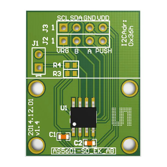
PUSH Output Pin Contactless pushbutton function output Adapter Board Description The AS5601 is connected over the dual-row 2.54mm 4-pin header footprint. Connect the desired pins of the AS5601 using the headers and resistors. Figure 1: Adapterboard Description Short J1 to operate in 3.3V mode... -
Page 5: Electrical Setup
Sensor Magnet (d6x2,5) AS5601 The magnet should be aligned by reading the output of the AGC register of the AS5601. For optimal alignment, the AGC value is in the middle of the AGC range. Note: If the magnetic field seen by the AS5601 is below 8mT, the output is disconnected and permanent angle programming is not possible. -
Page 6: Incremental Mode
Note: To use the push-button functionality AS5601 Configuration All options to configure the AS5601 are shown below. To use the AS5601 in incremental mode for a contactless rotary knob, the electrical signal must be aligned with the mechanical grid. As well the push-button threshold must be configured for the mechanical setup. -
Page 7: Configuring The Grid Push Button Threshold
0xFF) can be used to permanently program a configuration. 6.3.1 Low Power Mode Three low power modes are available to reduce the power consumption down to 1,5mA max. ams Eval Kit Manual, Confidential Page 7 [v1-00] 2014-Jul-31 Document Feedback... -
Page 8: Hysteresis
6.3.5 Watchdog If the watchdog is active, the AS5601 automatically enters Low Power Mode 3 after one minute if the output value stays within a threshold of 4 LSB. -
Page 9: Layout And Board Dimensions
J1=OPEN: 5V Adapterboard can be used with J1=CLOSED: 3.3V (Use 4pin I2C header in 3.3V m Note4: AS5601 I2C Address is 0x36h Note3: Note2: Optional pull-ups not populated Adapterboard can be used with AS5XXX-UCB-1.0 (Use 4pin I2C header in 3.3V mode) -
Page 10: Evaluation Tools
Smart Encoder IC Evaluation tools To configure the AS5601, no dedicated programmer is needed. For fast setup time the USB I&P Box can be used to configure the AS5601 over I C. The USB I&P Box can be ordered from the ams webpage. -
Page 11: Ordering & Contact Information
AS5601 Adapter Board Ordering & Contact Information Ordering Code Description AS5601-SO_EK_AB AS5601 Eval Kit Adapter Board Buy our products or get free samples online at: www.ams.com/ICdirect Technical Support is available at: www.ams.com/Technical-Support Provide feedback about this document at: www.ams.com/Document-Feedback For further information and requests, e-mail us at: ams_sales@ams.com... -
Page 12: Copyrights & Disclaimer
AG shall not be liable to recipient or any third party for any damages, including but not limited to personal injury, property damage, loss of profits, loss of use, interruption of business or indirect, special, incidental or consequential damages, of any kind, in connection with or arising out of the furnishing, performance or use of the technical data herein. -
Page 13: Revision Information
Initial version 1-00 Changes from 0-01 (2014-Jun-26) to current revision 1-00 (2014-Jul-31) Page Initial revision Note: Page numbers for the previous version may differ from page numbers in the current revision. ams Eval Kit Manual, Confidential Page 13 [v1-00] 2014-Jul-31 Document Feedback...
Need help?
Do you have a question about the AS5601 and is the answer not in the manual?
Questions and answers