Table of Contents
Advertisement
Quick Links
User Manual
________________________________________________________________________________
Automatische Mess- und
Steuerungstechnik GmbH
91275 Auerbach • Enge Gasse 1
91270 Auerbach • Postfach 1180
________________________________________________________________________
Subject to technical changes
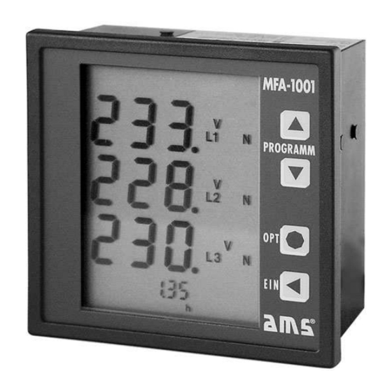
MFA 1001
Universal Multifunction Meter
Phone +49 (0) 96 43 / 92 05 - 0
Telefax +49 (0) 96 43 / 92 05 - 90
UM 800.01
Internet: www.ams-messtechnik.de
e-mail: info@ams-messtechnik.de
Rev.: 19.07.2006
Advertisement
Table of Contents

Related Manuals for AMS MFA 1001


Summary of Contents for AMS MFA 1001
- Page 1 User Manual MFA 1001 Universal Multifunction Meter ________________________________________________________________________________ Automatische Mess- und Steuerungstechnik GmbH 91275 Auerbach • Enge Gasse 1 Phone +49 (0) 96 43 / 92 05 - 0 Internet: www.ams-messtechnik.de 91270 Auerbach • Postfach 1180 Telefax +49 (0) 96 43 / 92 05 - 90 e-mail: info@ams-messtechnik.de...
-
Page 2: Table Of Contents
Table of contents page Product description ................ 3 Application..................3 Working principle ................3 Calibration ..................3 Installation and Starting up ............3 Installation notes ................3 Inputs, outputs and interfaces ............4 Possible connections ................ 5 Operation ..................5 Controls ..................... -
Page 3: Product Description
The impulse ratio is proportional to the active energy. On request the MFA 1001 can be equipped with a separate input to connect an auxiliary power supply (230 V AC). -
Page 4: Inputs, Outputs And Interfaces
Connections: All connections of the MFA 1001 are situated on the back of the casing. The block terminals are using screws to ensure safe and reliable connections with the network. For your attention ! ■ Voltages above the permitted voltage range can destroy the device! ■... -
Page 5: Possible Connections
Possible connections Operation Controls The multifunction meter is operated by 4 control keys:... -
Page 6: Display Layouts
When in display mode the 4 keys serve as hotkeys to activate pre-programmed display combinations. When in setup mode the keys are used to select the desired menus or program the device. Key T2( ↓ ) moves the display mode of the three main displays up one position, the key T1 ( ↑ ) moves down one position. -
Page 7: Additional Display
Setup General notes When using the multifunction meter for the first time in a specific environment the MFA 1001 needs to be adapted to the attached periphery using the setup mode. To activate setup mode press both the T1 and T2 key simultaneously for at least 3 seconds. -
Page 8: Possible Parameters And Factory Presets
Possible parameters and factory presets Description Adjustment range Factory presets Primary voltage transformer Identification plate, 400 V AC 1 V ... 999 kV 400 V Secondary voltage transformer Identification plate, 400 V AC 400 V 400 V (fixed setting) Primary current transformer Identification plate, 5 A / 1 A 1 A ... -
Page 9: Setting The Current Transformer Translation Ratio
Setting the current transformer translation ratio General notes: Only current transformers with a secondary value of 1 A or 5 A can be connected to the MFA 1001. The setup menu is used to select the type of current transformer (primary and secondary current) in use. -
Page 10: Setting The Switched Output (Optional)
Setting the switched output (optional) General notes: The MFA 1001 is shipped with a switched output as an optional extra. The output can optionally be used as a switched limit value output or as an impulse output. Switched limit value output:... - Page 11 Connection example: Switched output setup: 1. Press the T3 (OPT) key to activate the setup mode („LIMIT 1 ADJUST“). 2. Press the T1 ( ↑ ) or T2 ( ↓ ) keys to set the parameters to be monitored. The following parameters can be selected: Voltage U „V“...
- Page 12 for current, frequency, power, power factor for accumulated active power, accumulated reactive no selection (phase-independent) power, power factor entire network, active energy, operating time After the selection has been made press the T3 (OPT) key to proceed to the next step. 4.
-
Page 13: Deleting And Resetting
■ For the switched output the latest set values for LIMIT 1 are used. For better support we recommend to keep written protocol about settings and changes! Deleting and resetting General notes: The following values stored by the MFA 1001 can be deleted: Description Display Memory Type... -
Page 14: Setting The Password
If the password is incorrect the device returns to display mode. The factory preset is “000”. If the password is set to “000” the MFA 1001 does not request a password and jumps directly to the setup menu. -
Page 15: Terminal Configuration
The process is completed by pressing T3 (OPT) key. The setup menu is displayed. Store the set parameters in the flash memory by pressing T4 and exit setup mode. Terminal configuration Auxiliary power source (see identification plate): 230 V AC, 45 ... 65 Hz -15% / +20%, max. -
Page 16: Technical Details
Technical details Measuring inputs Voltage inputs Measuring range, 340 ... 400 ... 475 V AC Phase - Phase, 196 ... 230 ... 275 V AC Phase – Zero without auxiliary power Measuring range, 40 ... 400 ... 475 V AC Phase - Phase, 23 ... - Page 17 Type of protection Front IP 52 according to IEC / EN 60529 Front with additional seal (optional) IP 65 according to IEC / EN 60529 Back IP 20 according to IEC / EN 60529 Interfering transmissions IEC / EN 61326-1 Interference resistance IEC / EN 61326-1 / A1, industrial use Climatic category...
-
Page 18: Dimension Drawing
For support please contact Automatische Mess- und Steuerungstechnik GmbH Enge Gasse 1 D-91275 Auerbach/Opf. Postfach 1180 D-91270 Auerbach/Opf. Phone +49 (0) 96 43 / 92 05 - 0 Telefax +49 (0) 96 43 / 92 05 - 90 e-mail info@ams-messtechnik.de...
Need help?
Do you have a question about the MFA 1001 and is the answer not in the manual?
Questions and answers