Table of Contents
Advertisement
Quick Links
Advertisement
Table of Contents

Related Manuals for Sonatest Sitescan D-50


Summary of Contents for Sonatest Sitescan D-50
- Page 1 Sitescan D-50 User's Guide 9/17/2014 Document Number: Issue 0 September 2014...
- Page 2 Sitescan D-50 user’s manual How to contact Sonatest? Visit our website: www.sonatest.com or contact our offices. Sonatest Limited (International) Sonatest Inc . (America) Dickens Road 12775 Cogburn Milton Keynes San Antonio, Texas MK12 5QQ 78249 England +44 (0)1908 316345 ...
-
Page 3: Disclaimers And Notices
Sitescan D-50 user’s manual Disclaimers and Notices The following information must be read and understood by users of the Sonatest Sitescan D-50 ultrasonic flaw detector and thickness gauge. Failure to follow these instructions can lead to serious errors in test results or damage to the flaw detector. Decisions based on erroneous results can lead to property damage, personal injury or death. -
Page 4: Testing Limitations
Critical Operating Factors The following procedures must be observed by all users of the Sitescan D-50 in order to obtain proper, accurate and consistent results. Calibration of the Sound Velocity... -
Page 5: Effects Of Temperature On Calibration
Sonatest Limited in connection with the use, features and qualifications of the Sitescan D-50 are based on tests believed to be reliable, but the accuracy or completeness thereof is not guaranteed. Before using the product you should determine its suitability for your intended use based on your knowledge of ultrasonic testing and the characteristics of materials. -
Page 6: Copyright
Sonatest Limited. Sonatest limited or its filial provides this manual “AS IS” without warranty of any kind, either express or implied. Included but not limited to the implied warranties or conditions of merchantability or fitness for a particular purpose. -
Page 7: Electromagnetic Compatibility
(3) meters in length. If this is necessary, the installation may require further EMC testing to ensure conformity. The Sitescan D-50 also complies with EN 12668-1, non-destructive testing and verification of ultrasonic examination equipment – Part 1: Instruments. For any questions relating to the proper... -
Page 8: About This Guide
Sitescan D-50 user’s manual About this guide How this guide is organised This guide contains the following parts: Chapter 1: Product Introduction Chapter 2: Detailed Menu Description Chapter 3: Flaw testing Chapter 4: Thickness Gauging ... -
Page 9: Table Of Contents
Convention used in this guide ................7 Typography ....................... 7 Chapter 1 : Product Introduction ................11 Welcome! ....................11 Features of the Sitescan D-50 ..............11 Functional Testing Methods ................11 Front Panel .................... 12 Back Panel ..................... 14 Sitescan D-50 Memory ................ - Page 10 Sitescan D-50 user’s manual Waveform Tab ....................36 User Keys Tab ....................37 MISC Tab 37 VIDEO Tab ....................... 38 BEA (Backwall Echo Attenuator) Tab ..............38 AGC (Automatic Gain Control) Tab ..............39 Encoder tab ..................... 40 CLOCK Tab ...................... 40 Storage &...
- Page 11 Sitescan D-50 user’s manual Interface Trigger IFT ................98 Immersion Testing .................... 98 Problems associated with immersion testing ............98 Backwall Echo Attenuator (BEA) ............. 102 Split Distance Amplitude Correction (Split DAC) ........104 Chapter 8 : Accessories ..................106 Lithium-Ion Battery Pack ..................
-
Page 12: Chapter 1 : Product Introduction
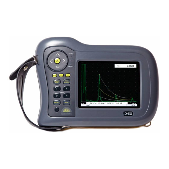
Features of the Sitescan D-50 The Sitescan D-50 is a user-friendly ultrasonic digital flaw detector and thickness gauge, which is simple to use and provides the experienced ultrasonic operator with a full-function device that incorporates many productivity enhancing features. -
Page 13: Front Panel
Sitescan D-50 user’s manual Front Panel The main control on the front of the unit is the scroll-wheel that is used to navigate through the [OK] menus and to adjust parameters this, along with the key in the middle of the wheel allows quick and intuitive navigation. - Page 14 Sitescan D-50 user’s manual [OK] After a parameter is selected, press shortly the button (valid only for parameters with windows [up] [down] sign) to open a list windows, arrows keys will move up and down the drop-down list. [OK] [up]...
-
Page 15: Back Panel
Sitescan D-50 user’s manual Back Panel The back panel is where the battery pack, the TX/RX and RX connectors (LEMO or BNC) are located. Additionally a quadrature encoder can be used with the unit when attach to the encoder connector. -
Page 16: Sitescan D-50 Memory
Sitescan D-50 user’s manual Sitescan D-50 Memory The settings of the Sitescan D-50 always remain in memory when the instrument is turned off, even if the battery pack is removed. That is, whatever the settings are just prior to turning the instrument off will be the settings in place the next time the instrument is turned on. -
Page 17: Key Names And Functions
Sitescan D-50 User’s Manual Key Names and functions Icon Function Name Short Function Description Power on & off push button for switching the instrument on and off. Operates as ON/OFF a toggle. This button operates in conjunction with the memory menus to accept a store or [OK]. - Page 18 Sitescan D-50 User’s Manual The full screen button is used to toggle between showing the A-Scan on the full Full screen display and showing it with the menus and parameter boxes. Full display is useful button for maximising the size of the A-Scan while performing inspections.
- Page 19 Sitescan D-50 User’s Manual Gain Down Press to decrement the gain value indicated in the gain box. This is always located at the bottom right side of the screen. This is a repeat button with acceleration to facilitate quick changing of the value.
-
Page 20: Chapter 2 : Detailed Menu Description
Main Menu When the Sitescan D-50 is switch on, the unit will perform an initial check test. And a similar screen will appear. During that test the screen may flick momentarily. When the test is finished the following screen should appears: As shown above the main menus are on the right hand side of the screen. -
Page 21: Cal Menu
Sitescan D-50 User’s Manual CAL Menu menu is the most used menu and contains those items that allow the Sitescan D-50 to be easily calibrated. For full instruction on how to perform a calibration see Flaw Testing Calibration. CAL (Calibration) Tab Probe zero: Used to calibrate the screen and thickness readout for zero offsets that are inherently different for each transducer. -
Page 22: Gate 1 & Gate 2 Tab
Sitescan D-50 User’s Manual Gate 1 & Gate 2 Tab Set the state of the gate as follows: OFF: Switches the gate off. ON +VE: The alarm triggers when an echo in the gate exceeds the threshold level. ON -VE: The alarm triggers when an echo in the gate falls below the threshold level. -
Page 23: Meas Menu
Sitescan D-50 User’s Manual MEAS Menu The menus in this section allow the various measurement techniques to be configured; these include the general measurement set-up and specialist methods such as DAC, AVG, TCG, AWS and API. MEAS MENU] Select the menu at any time by pressing the [ button. - Page 24 Sitescan D-50 User’s Manual Meas Mode (G1-G2) This is similar in concept to E-E mode, but uses gates 1 & 2, allowing the thresholds for the two gate measurements to be completely independent. Meas Mode (F-F): In this mode gates 1 and 2 take measure from one Flank to another Flank.
-
Page 25: Trig Tab
Sitescan D-50 User’s Manual Trig Tab Surface: allows you to choose CONCAVE for internal surfaces or CONVEX for external surfaces. For flat surface with no curvature set this option to Flat When 1/2 Skip is ON, this parameter is used as a quick way to turn on the ½ skip graticule which display dotted lines on the display representing half skip, full skip and skip and Half. -
Page 26: Dac (Distance Amplitude Correction) Tab
Sitescan D-50 User’s Manual DAC (Distance Amplitude Correction) Tab This menu is used to create DAC curves using a series of reference echoes. Once drawn, the DAC curve acts as an alarm threshold level for the gate where the level varies to match the attenuation and field characteristics of the transducer and test material combination. -
Page 27: Tcg (Time Corrected Gain) Tab
Sitescan D-50 User’s Manual TCG (Time Corrected Gain) Tab This menu is used to create TCG curves using a series of reference echoes. Once drawn, the TCG curve acts as swept gain control on the amplifier to set different gain levels relative to distance. The... -
Page 28: Avg (Amplituden Vergleichs Größe) Tab
Sitescan D-50 User’s Manual AVG (Amplituden Vergleichs Größe) Tab This menu is used to create a DGS/AVG curve allowing flaw sizing and distance compensation without requiring the reference standards for establishing a DAC curve or to set up a TCG correction. - Page 29 AVG Mode (Set SIG): Mode used to perform calibration Cursor (mm): Select than use the [Up] and [Down] navigation arrow button to move the selection over the echo and press [OK]. The Sitescan D-50 will calculate the sensitivity and draw the curve on the screen.
-
Page 30: Api (American Petroleum Institute) Tab
Sitescan D-50 User’s Manual API (American Petroleum Institute) Tab This menu is used to assist users in performing tests according to the American Petroleum Institute (API) Recommended Practice for Ultrasonic Evaluation of Pipe Imperfections using the Amplitude Distance Differential Method (ADDM). Users are referred to the publication: “API Recommended Practice 5UE, Second Edition, June 2005”... -
Page 31: Aws (American Welding Society) Tab
Sitescan D-50 User’s Manual AWS (American Welding Society) Tab This menu is used when performing weld inspection in accordance with the American Welding Society’s Structural Welding Code, ANSI/AWS D1.1-94. It provides a convenient method to automatically calculate the Indication Rating as defined in the code. The AWS procedure is... -
Page 32: Bchart Tab
Sitescan D-50 User’s Manual BChart Tab Bchart mod (Off/Timed/Encoded): Used to set up the AWS measurement mode. BChart mod: When set in Time the BChart is activates and begins collecting data to display the BChart based on time. LOS (dB): This option allows the choice between STOP and CONTINUE, it determines what the Sitescan should do when a Loss Of Signal occurs. -
Page 33: Memory Menu
Sitescan D-50 User’s Manual MEMORY Menu MENU] [OK] Press the [ button then the button when the Menu is highlighted to gain access to panel settings, A-Scans (A-Log) B-Scans the tabs and sub-menus. These Tabs allow the user to save... -
Page 34: Ref Tab
Sitescan D-50 User’s Manual REF Tab This menu allows a waveform stored in A-LOG memory to be displayed as a reference on the display. Before a waveform can be recalled, it must be stored in an A-LOG location as described above. -
Page 35: T-Log Tab
Sitescan D-50 User’s Manual T-LOG Tab Mode (off) : In this mode the T-log is disabled, it is possible to access the setup features of the grid T-log mode (if feature purchased) T-Log Mode (file): When mode is set to file, it allows the user to save a thickness log in the same way an A-log or a B-log is saved. -
Page 36: Grid Tab
Sitescan D-50 User’s Manual Grid Tab Mode (off): In this mode the Grid Log is disabled. Mode (file): When mode is set to file it allows the user to save a thickness log in the same way an A-log or a B-log is saved. -
Page 37: Util Menu
, encoder as well as date and time settings. MENU Tab Language: Selects one of 6 built in languages or a user selectable language. The built in languages are selectable at time of ordering the Sitescan D-50. Units: Selects , or measurement units. -
Page 38: User Keys Tab
Sitescan D-50 User’s Manual User Keys Tab UserKey 1, UserKey 2, UserKey 3 and UserKey 4: these four USER buttons can be assigned to any parameter on the Sitescan. The followings quick access functions can be assigned from any of the Userkey parameters: Panel: ... -
Page 39: Video Tab
Sitescan D-50 User’s Manual VIDEO Tab Colour: Selects one of eight colour schemes (signal, Menu, highlight) for the display. The colour schemes are as follow: Green, Blue, Black (default) Black, Black, White White, Black, White Yellow, Black, Yellow Yellow, Black, White... -
Page 40: Agc (Automatic Gain Control) Tab
When the Sitescan D-50 is switched on the AGC is turned OFF. The gain value that is last set by AGC remains when AGC is switched off. -
Page 41: Encoder Tab
Sitescan D-50 User’s Manual Encoder tab Encoder: When set in manual the user will be able to the selected value set the resolution of the encoder as well as the direction of the encoding. When set in Auto the encoder resolution will be set a 14.40 clicks and Bchart option has to be set on encoded. -
Page 42: Storage & Recall Of Calibration Setups
Storage & Recall of Calibration Setups After the Sitescan D-50 has been properly calibrated for a particular testing scheme, it is possible to store all of the panel settings for subsequent recall when performing the same test at a later time. - Page 43 Sitescan D-50 User’s Manual [OK] Step 4: Once the button has been pressed a window will appears as shown below. [OK] Step 5: Press the Button to create a new panel settings. Step 6: The screen as shown below should appear. Enter the details for the panel to be saved.
-
Page 44: How To Recall A Panel Set
Sitescan D-50 User’s Manual How to recall a panel set? [Menu] [up] [down] Step 1: Press button then highlight menu using navigation arrow key. [OK] When menu is highlighted press the button. [left] [right] navigation arrow Panel Step 2: Use the buttons to highlight the Tab. -
Page 45: Adding Notes To Panel And A-Log Sets
Sitescan D-50 User’s Manual Adding NOTES to PANEL and A-LOG sets When storing panel calibration settings or waveforms, it is often useful to add some notes to the set PANEL so it can later be identified, or to help the user recall the correct set. This is possible in the... -
Page 46: Edit Notes Summary
Sitescan D-50 User’s Manual Edit Notes Summary The following sections provide a summary of the navigation techniques needed to edit notes using either the front panel keypad. In this case we assume the file note has already been saved Press to bring up the editing boxes as follows:... -
Page 47: Chapter 3 : Flaw Testing
Fabricated discontinuities must also be placed near the front and back surface of the calibration block to verify resolution of the transducer and instrument setting combination. Finally, it is necessary to establish the proper calibration of the Sitescan D-50 in order to assure reliable flaw detection. -
Page 48: Flaw Tester Calibration
The essence of this calibration is to set the pulser, amplifier and gate parameters to provide the necessary sensitivity and resolution. The Sitescan D-50 has an automatic calibration technique that sets the necessary parameters by using a calibration block that has known thicknesses; see Auto-Cal for details. - Page 49 Sitescan D-50 User’s Manual the material will not match one of the preset values. Select a velocity that is close to the material then adjust it so that the exact distance is obtained as shown below: To set any parameters manually such as velocity. Press and hold the [OK] button then ...
- Page 50 Check that the correct values are shown as below: Now that the Sitescan D-50 has been calibrated it can be used to perform inspections using any of the techniques described in the following sections.
- Page 51 Sitescan D-50 User’s Manual Perform the following steps to establish a basic flaw detection mode for the Sitescan D-50. 1. Select a suitable single element contact transducer, preferably a 5MHz, 10mm diameter narrow band and calibration block that matches the material and expected discontinuities under test.
-
Page 52: Chapter 4 : Thickness Gauging
This will allow for verification of the calibration. It is possible to calibrate the Sitescan D-50 using a generic test block and only one known sample thickness of the material under inspection. This is a less desirable method because there is no way of verifying the calibration. -
Page 53: Thickness Gauging Calibration
Sitescan D-50 User’s Manual Thickness Gauging Calibration Finally, it is necessary to establish the proper calibration of the Sitescan D-50 in order to assure accurate and reliable thickness testing. The essence of this calibration is to set the pulser and amplifier characteristics to provide sharp leading edges on the echoes. - Page 54 Interface to first return echo. Multiple echo mode which usually measures from the first to the second return echoes after the interface echo. The Sitescan D-50 with Advanced Thickness provides two multiple echo measurement modes: a) Echo – Echo ( E-E) ...
- Page 55 8. Calibrate the thickness readout on the selected calibration block using the procedure in Auto- Cal. The Sitescan D-50 is now configured for basic thickness gauging. Adjust parameters as necessary to optimize the calibration. For more in-depth features of the Sitescan D-50, see Advanced Thickness Mode section.
-
Page 56: Auto-Cal
The AUTO-CAL feature automates this process so that only two readings are required, one on the thin sample and one on the thick sample. The Sitescan D-50 then calculates the correct offset and span factors and sets the velocity and zero. Any time the test material is changed (velocity) or the transducer is changed (zero);... -
Page 57: Tcg For Reliable Gauging
Note that this is a convenient method for determining the velocity of sound in an unknown material. Once the Sitescan D-50 is calibrated on a known material, all that needs to be known is one fixed thickness point and the velocity can be determined. -
Page 58: Thickness Logging Without Grid
Sitescan D-50 User’s Manual Thickness Logging Without Grid A Sitescan D-50 without the Corrosion and Grid option will have certain options disabled. It is not possible to load user specified notes, sequence text or old readings into the Sitescan. On top of this, it is not possible to store A-Scans with thickness readings. -
Page 59: Chapter 5 : Standard Features
To establish a DAC curve, follow these instructions: Establish the basic calibration of the Sitescan D-50 using the desired transducer and the proper MEAS Sizing reference block. From the menu, go to tab to select the DAC feature. - Page 60 Sitescan D-50 User’s Manual [MENU] [Up] Press to come out of the adjust parameter then use the key to move to the Mode [OK] [Down] box, use the button to display the drop down list then use the to select...
- Page 61 Sitescan D-50 User’s Manual These additional, automatically generated, reference curves provide a method for helping to evaluate discontinuities smaller than those in the reference block. Trigger Use the parameter to select the alarm trigger from Gate 1, the DAC curve, or any of the additional curves listed in the curve parameter above that are currently selected.
-
Page 62: Temperature Compensation
Sitescan D-50 User’s Manual Temperature Compensation Over view The Sitescan D-50 provides, as a standard option a “temperature compensation feature” (T-COMP) to enable measurements to be corrected for a temperature disparity between a calibration block MEAS and the actual material under test. This feature can be found under the menu group. -
Page 63: Using Temperature Compensation
Sitescan D-50 User’s Manual Once this feature has been set up, measurements are automatically corrected and shown in both the measurement lines and the HUD. Using Temperature Compensation Once the calibration procedure has been carried out, temperature compensation can be switched on. -
Page 64: Weld Inspection Using Trigonometry Mode
Essentially, the trigonometry mode uses the thickness gauging features of the Sitescan D-50 to calculate the surface distance and depth to a discontinuity from the actual beam path measured. This is accomplished by calibrating the trig mode with the actual refracted angle of the transducer being used. - Page 65 Sitescan D-50 User’s Manual To calibrate and use the trigonometry mode, follow the following instructions: Using a suitable IIW or other calibration block, measure and establish the central sound beam exit point and actual refracted angle for the transducer being used.
-
Page 66: Flank- Flank Measurement Mode
Sitescan D-50 User’s Manual Flank- Flank Measurement Mode Overview This measurement mode, called Flank to Flank (F-F) measures the distance between the first rising flank through gate 1 and the second rising flank through gate 2. This mode is designed for use within the Thickness Measurement area of NDT. -
Page 67: Using Flank - Flank Mode
Sitescan D-50 User’s Manual It should be noted that automatic levelling of Gate 2 is dependent on the peak echo through Gate 1, thus if there is a number of echoes traversing Gate 1, the measurement will be taken from the first rising flank, but the amplitude (for calculating the correct height of Gate 2) will be taken from the peak within that gate (which might not be the same echo). -
Page 68: A-Log, A-Scan Storage
Simply unfreeze the display after recalling and the Sitescan D-50 is ready to repeat the same inspection. Be sure to use the same transducer that was used for the original recording. -
Page 69: How To Recall An A-Scan
Sitescan D-50 User’s Manual Use the Scroll-Wheel to select the location to store the A-Scan. [OK] Pressing the button opens the NOTES window to allow the input of notes for the stored A- Scan and its settings. ... -
Page 70: How To Delete A Stored A-Scan
Sitescan D-50 User’s Manual How to Delete a Stored A-Scan A-Log Load A-Log From the MEM menu, go to Tab then select the feature. Load A-log [OK] When is highlighted press button. The list of available saved scan is the same as that for saving an A-Scan. -
Page 71: Contour, Peak Echo & Hold Dynamics
Sitescan D-50 operate more like an older analogue flaw detector. Only the trailing edge is modified so that depth measurements using FLANK and PEAK are not affected. - Page 72 This is a quick and useful to way to make comparisons between echoes. [Freeze/Peak] Hold mode can be activated by pressing the button four times. Pressing the [Freeze/Peak] button again will return the Sitescan D-50 to its normal mode of operation.
-
Page 73: B-Chart Measurement Technique
B-Chart Measurement Technique Overview The Sitescan D-50 provides B-chart functionality as an extension to the Grid thickness Logging mode. The Sitescan units do provide an encoder input, so the B-chart can be time-based or encoded bases. A B-chart can be used to graphically show an internal wall profile. -
Page 74: Using B-Chart Mode
Sitescan D-50 User’s Manual N.O.S parameter refers to the “Number of Samples‟ stored in the B-Chart; 500 is the maximum, with one pixel line per sample. Once the above parameters have been chosen, the B-chart will appear below if the transducer is set Speed N.O.S... - Page 75 Sitescan D-50 User’s Manual The minimum thickness (depth) in the currently shown B-Chart is displayed in the bottom left corner. Shown above is an example B-Chart. The user is expected to select an appropriate scanning Speed speed related to the parameter.
-
Page 76: Bchart, Bchart Storage
Sitescan D-50 User’s Manual BCHART, Bchart Storage The storage functionality in the Sitescan D-50 has been extended to support the storage of B-Chart. The extended functionality has been implemented into Utility in order to allow the B-Chart to be read out and display, stored or added to a report. - Page 77 Sitescan D-50 User’s Manual It is possible to overwrite a location – the Sitescan will ask for confirmation from the user before writing the data to memory. FREEZE/PEAK The [ ] key can be used to delete the currently selected store.
- Page 78 Sitescan D-50 User’s Manual The storage success can be checked by viewing the list of stores again: It is also possible to review the stored B-Chart on the Sitescan in the same way that an A-Scan can be reviewed. It is not possible to load a B-Chart as a reference trace though and like the A-Scan review the B-Chart is lost once freeze mode is released.
-
Page 79: Chapter 6 : Interface Connection
USB connector There is a 6-pins connector under the black cover on the rear of the Sitescan D-50 as shown below: This connector is used to connect the flaw detector to a PC using a modified USB cable; this allows information to be transferred to the computer using Sonatest’s program UT-lity. -
Page 80: Chapter 7 : Optional Features
Sitescan D-50 User’s Manual Chapter 7 : Optional Features Entering License Key to Activate Options The Sitescan software contains the optional features as standard but require a license key in order to enable them. License keys can be obtained for the (paid for) optional features by contacting your local distributor. -
Page 81: Time Correction Gain (Tcg)
To establish a TCG curve, follow the following instructions: Step 1: Establish the basic calibration of the Sitescan D-50 using the desired transducer and the proper reference block. - Page 82 Sitescan D-50 User’s Manual Step 7: Repeat steps 5 and 6 for each additional reference hole in the reference block, being careful to be consistent with the amount of coupling and transducer pressure. A maximum of 10 points can be recorded for a TCG curve.
-
Page 83: Distance Gain Size (Dgs)/Amplituden Vergleichs Größe (Avg)
Sitescan D-50 User’s Manual Distance Gain Size (DGS)/Amplituden Vergleichs Größe (AVG) The DGS (Distance Gain Size) method, often known by its German acronym AVG (Amplituden Vergleichs Größe), allows a theoretical model to be used for assessment of ultrasonic echoes. The DGS/AVG method allows flaw sizing and distance compensation without requiring the large range of reference standards for each test which would be required in order to establish a measured DAC curve, or to set up a TCG correction. -
Page 84: Theory
Sitescan D-50 User’s Manual Theory For a naturally focussed probe of given frequency and size, the general beam profile can be defined in terms of a ‘normalised’ standard curve, scaled by the Probe ‘effective diameter’ and near field length. The near field length is defined by the equation:... -
Page 85: Dgs/Avg Frequency, Nfl And Ers
Sitescan D-50 User’s Manual DGS/AVG Frequency, NFL and ERS Highlight and select MEAS menu (press [Menu] button then [OK] when highlighted) From Sizing tab select AVG, AVG Tab should appears next to it. AVG MODE OFF. Select the tab, its... -
Page 86: Dgs/Avg T-Loss, Ref Db And Mat Db
Sitescan D-50 User’s Manual DGS/AVG T-Loss, Ref dB and Mat dB AVG MODE SET ATT Change sub-menu to ‘ ’. This menu allows the operator to enter attenuation parameters relating to the materials of the Calibration Block and the item under test, these... -
Page 87: Dgs/Avg Dvk, Ref Type And Refsize
Sitescan D-50 User’s Manual DGS/AVG dVK, REF TYPE and REFSIZE MODE SET REF Change dVK (V – Curvature Correction Factor in dB This value allows the use of a curved surface to provide a back wall echo for use as a reference signal, thus the same reference block can be used irrespective of probe angle. - Page 88 Sitescan D-50 User’s Manual Ref Size – Reference Reflector Size, diameter in mm. The Reference Reflector Size parameter allows the user to enter the diameter of the reference Ref Type reflector. The reflector type is set using the parameter above.
-
Page 89: Dgs/Avg Calibration (Set Sig)
Sitescan D-50 User’s Manual DGS/AVG Calibration (SET SIG) The calibration of the DGS/AVG system sets the Probes ‘absolute sensitivity’ based on the response from the reference block. Changing any parameters relating to the reference echo will invalidate the calibration, which must then be repeated. -
Page 90: Adjustment
Sitescan D-50 User’s Manual Adjustment When the DGS/AVG has been calibrated it is possible to leave the DGS/AVG menus and adjust other settings of the instrument, for example range and gate settings. Gain may be adjusted with understanding – Changing the Gain setting will remove the correlation with the DGS/AVG curve, so should only be done in accordance with a specification , for example to compensate for varying material conditions (better done with the T-LOSS function). -
Page 91: Measurement
Sitescan D-50 User’s Manual [dB] The Reference gain may be selected by pressing the Button. (DGS/AVG is only appropriate for Single probe mode) Range Ref Gain When the display is changed the DGS/AVG curve will recalculate at each step. If... -
Page 92: American Welding Society (Aws)
T-LOG API or AGC To set up the AWS measurements, perform the following: 1. Calibrate the Sitescan D-50 for weld testing and set up the trigonometry mode by following the steps in Weld Inspection Using Trigonometry Mode. MEAS... - Page 93 It is not necessary to bring the indication to the reference level to obtain the correct measurement information as the Sitescan D-50 adjusts for gain offset. However, to ensure the best accuracy of calculation, it is advised to adjust the indication to be above 40% and below 100% of full screen height.
- Page 94 Sitescan D-50 User’s Manual Once AWS has been switch to mode it is no longer possible to adjust the reference gain. AWS can be operated in full screen mode, as shown below: [FULL With AWS active it is possible to maximise the screen height by pressing and holding the SCREEN] key, this will remove the HUD but leave AWS active.
-
Page 95: Evaluating Pipe Imperfections Using American Petroleum Institute (Api) 5Ue94
The first step is to perform ‘standardisation’ using a reference indicator such as a notch at a known depth or a through drilled hole. It is assumed that the Sitescan D-50 has been setup with the correct values for the transducer and specimen under inspection. - Page 96 Sitescan D-50 User’s Manual [MENU] Pressing the button will cancel the calibration and return to previous screen – this will also [OK] clear the peak envelope. Pressing the button will accept the K Factor that has been calculated API MODE...
- Page 97 Sitescan D-50 User’s Manual Hold The Sitescan D-50 is automatically put into mode once a measurement has been taken. The resulting di value is shown highlighted in the HUD – if it was unable to calculate the di value, dashes...
-
Page 98: Grid Thickness Logging
Sitescan D-50 User’s Manual Grid Thickness Logging Please see separate manual for details... -
Page 99: Interface Trigger Ift
Sitescan D-50 User’s Manual Interface Trigger IFT The Sitescan D-50 has an interface trigger allowing the unit to be used for immersion testing, testing using a water jet as a couplant or testing using water filled wheel probes. The interface trigger is an additional gate that is dedicated to the interface trigger functionality. - Page 100 Sitescan D-50 User’s Manual It is therefore essential that the water gap chosen be over a 1/4 of the steel test specimen's maximum thickness to ensure that the water / steel interface echo does not repeat before the first back wall echo from the specimen.
- Page 101 To overcome unwanted gate triggering during testing caused by fluctuation in the water gap, an interface trigger is incorporated into the Sitescan D-50. The user is able to set the gate in terms of position in time, amplitude and width; once these settings have been made the user can switch IFT on and off at will.
- Page 102 Sitescan D-50 User’s Manual If the interface trigger is lost for any reason for instance moving beyond the end of the test specimen or lifting the wheel probe off the specimen the trigger stops, the trace freezes and a message is...
-
Page 103: Backwall Echo Attenuator (Bea)
Sitescan D-50 User’s Manual Backwall Echo Attenuator (BEA) The backwall echo attenuator allows the gain to be independently adjusted over a defined area of UTIL the A-Scan. To enable the backwall echo attenuator, select the main menu followed by the... - Page 104 Sitescan D-50 User’s Manual Once the backwall Echo attenuator is the size of the attenuator can be changed by adjusting the ATTEN parameter. The maximum area over which the backwall attenuator can be active is 50% and the maximum attenuation is the same as the available gain up to a maximum of 40dB.
-
Page 105: Split Distance Amplitude Correction (Split Dac)
To establish a Split DAC curve, follow the instructions: Establish the basic calibration of the Sitescan D-50 using the desired transducer and the proper MEAS Sizing reference block. From the menu, go to tab to select the DAC feature. - Page 106 Sitescan D-50 User’s Manual Repeat steps 4 and 5 for each additional reference hole in the reference block, being careful to be consistent with the amount of coupling and transducer pressure. A maximum of 10 points can be recorded for a DAC curve.
-
Page 107: Chapter 8 : Accessories
Use the battery only with the Sitescan D-50 for which it is specified. Never use a battery with any other equipment, or for any purpose that is not specified in this instruction... -
Page 108: Battery Charging
10 (the default) or for 9 hours with a brightness of 20. The battery pack can be charged while mounted to the Sitescan D-50 by use of the connector on the front panel. Alternately, the battery pack can be charged separate from the by using its own connector shown above allowing continued operation of the Sitescan D-50 with the use of multiple battery packs. -
Page 109: Battery Charger
2.0 Amps. The part number for a battery pack is 212173. The CH700 is a battery charger only. Any attempt to use it to power a Sitescan D-50, without a battery fitted, WILL damage your CH700-P battery charger. -
Page 110: Chapter 9 : Products Specifications
Sitescan D-50 User’s Manual Chapter 9 : Products Specifications (Subject to change without notice) Features Details Enclosure Size H=172mm x W=238mm x D =70 mm (6.77 in x 9.37 in x 2.75 in) Weight 1.7 Kg (3.7 Lbs) with battery... - Page 111 Sitescan D-50 User’s Manual Others features ActiveEdge™ Used to improve the pulse shape and improve near- surface resolution. Rectification Full wave, positive or negative half-wave and unrectified RF. Gate Monitor Two fully independent gates for echo monitoring and thickness measurement. Start and width adjustable over full range of unit, amplitude variable from 0 to 100% FSH.
- Page 112 Sitescan D-50 User’s Manual Internal memory 4 GByte storage available Receiver Connector type BNC or LEMO 1 (factory option) gain range 0 to 110 dB, adjustable in 0.1, 0.5,1,2,6,10,14 and 20dB steps. Direct access to gain control at all times...
-
Page 113: Chapter 10 : Warranty
Sonatest. Sonatest will make good by repair or by the supply of a replacement or by equivalent adjustment of the price at our sole option, any defects which under proper use appear in the goods within the... -
Page 114: Chapter 11 : Troubleshooting And Support
Sitescan D-50 User’s Manual Chapter 11 : Troubleshooting and Support Q1 – My Sitescan Unit does not start when press [Power] button? Make sure the battery is fully charged and connected to the Sitescan. If the battery is flat or not fully charge connect the charger which came with the unit. - Page 115 Sitescan D-50 User’s Manual Q6 – Memory does not store or recall data? Using the CLOCK tab check the time settings. If it incorrect then set the time and Date. If the time and date will not keep when the unit is switch off or you get DATA error message try restoring factory defaults.
-
Page 116: Chapter 12 : Maintenance
Sitescan D-50 User’s Manual Chapter 12 : Maintenance Casing Do not put the flaw detector near a source of electromagnetic noise, which could disrupt data acquisition. If you have carpets in your work place, be careful about electrostatics shocks. -
Page 117: Chapter 13 : Index
Sitescan D-50 User’s Manual Chapter 13 : Index Contact · 6, 11, 47, 48, 52, 96, 110 Contour · 85 Controls · 39 Convex · 24 A-CAL Menu · 21 Corrosion · 52 Adjustment · 84 Couplant · 4, 96 AGC ·... - Page 118 Sitescan D-50 User’s Manual Flaw Detection · 3, 11 Main Menu Selection · 19 Flaw Detection Calibration · 3 MEAS · 19, 22, 24, 40, 48, 49, 51, 54, 55, 56, 57, 59, 60, Flaw Detector · 2, 3, 11, 73, 96, 97 65, 75, 86, 89, 90, 102 Flaw Testing Calibration ·...
- Page 119 Sitescan D-50 User’s Manual Temperature Variations · 4 Test Blocks · 3, 4, 52, 57, 86 Testing Limitations · 3 Qualification · 2 Theory · 77 Thickness Gauge · 2, 11 Thickness Gauging · 55 Threshold · 21, 22, 26, 30, 58, 59, 102 Time Corrected Gain ·...
- Page 120 Sitescan D-50 User’s Manual Zero · 3, 20, 21, 52, 57, 58, 65, 79, 82, 85...
- Page 121 Sitescan D-50 user’s manual Document Number Issue 0 July 2014...
Need help?
Do you have a question about the Sitescan D-50 and is the answer not in the manual?
Questions and answers
How to create a grid table for thickness measurement using the D-50
To create a grid table for thickness measurement with the Sonatest Sitescan D-50:
1. Without Corrosion and Grid Option:
- Cannot store A-scans with thickness readings.
- Cannot load user notes, sequence text, or old readings into the device.
- 1D and 2D grids can be configured using Utility software, but not directly on the device.
- You can input a PLAN NAME and PLAN DESCRIPTION.
- Adjust grid size and increment direction using the Utility software.
2. With Grid Option Enabled:
- Go to the Grid Tab and set Mode to "file" to enable T-Log grid saving.
- To save a T-Log grid: Highlight "Save T-Log grid" and press [OK].
- To load a T-Log grid: Highlight "Load T-Log grid" and press [OK].
- To edit notes: Highlight "Edit Notes" and press [OK] to associate a note with the T-Log.
This allows managing thickness data in a grid format for better organization and analysis.
This answer is automatically generated