Table of Contents

Related Manuals for Carrier 38HB series


Summary of Contents for Carrier 38HB series
- Page 1 INSTALLATION, OPERATION AND M A I N T E N A N C E I N S T R U C T I O N S Split-system units 38HB/HF Nominal cooling capacity 19,3 - 36,9 kW Nominal heating capacity 22,3 - 41,9 kW 50 Hz Translation of the original document 80127, 07.2015...
-
Page 2: Table Of Contents
Split-system cooling units and heat pumps Contents 1. Introduction ........................................3 2. Operating limits .........................................3 3. Technical characteristics (EN-14511-2013) ..............................4 4. Unit identifi cation .......................................5 5. Safety advice ........................................5 6. Transport ...........................................6 7. Location and assembling ....................................6 Choise of location ......................................6 Sound level ........................................7 Anchorage for silent-blocks ....................................7 Minimum free space for commissioning and maintenance operations (mm) ....................8... -
Page 3: Introduction
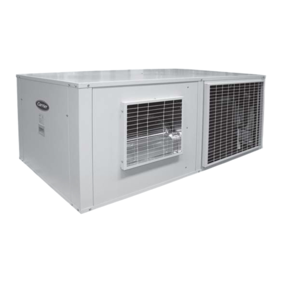
2. O PERATING LIMITS • 38HB/HF series 38HB series: Outdoor unit cooling-only air-condensed with Inlet air conditions Cooling Heating centrifugal fan, horizontal design, designed for installation indoors. -
Page 4: Technical Characteristics (En-14511-2013)
Split-system cooling units and heat pumps 3. T (EN-14511-2013) ECHNICAL CHARACTERISTICS 38HB/HF 19,3 21,2 27,3 36,9 Cooling capacity (kW) Cooling Power input (kW) 11,5 14,2 capacities EER performance 2,40 2,20 2,38 2,60 22,3 24,2 32,0 41,9 Heating capacity (kW) Heating ... -
Page 5: Unit Identifi Cation
Temperature Maxi C BP Mini PSM\MOP Intensité\Current A No CE HP Maxi PSM\MOP Int. Kit Elect. 0056 CARRIER SCS UTC BIS Route de Thil P.I. Llanos de Jarata 14550 Montilla - SPAIN 01122 Montluel–France Phone: 34 957 65 23 11 Tél: 33(0)4 72 25 21 21... -
Page 6: Transport
Split-system cooling units and heat pumps 6. T RANSPORT The unit must be handled with care to avoid transport damage. Thus Outdoor unit we recommend: 38HB/HF - Do not dispose of the transport supports or the packaging materials until the unit is in its fi nal location. - For transport in a container, one must be selected that has an easy load and unload to the installation location. -
Page 7: Sound Level
Split-system cooling units and heat pumps Sound leve l These units have been designed to operate with a low sound level. In any case, in the design of the installation, it must be taken into consideration: the outdoor environment for the acoustic radiation, the type of building for the noise transmitted in the air and the solid elements for the vibration transmission. -
Page 8: Minimum Free Space For Commissioning And Maintenance Operations (Mm)
Split-system cooling units and heat pumps M inim um fre e spa c e for c om m issioning a nd m a int e na nc e ope rat ions (m m ) Outdoor unit 38HB/HF Indoor unit 40HB/HF 8. -
Page 9: Condensate Drain Connection
Split-system cooling units and heat pumps Connection chart Siphon installation norms All water drain tubes must be provided with a siphon to avoid bad smell and water spills. Pan in overpressure: Power supply TCO user terminal - It’s installed to avoid the access through the drain piping of bad smells. pGD1 maintenance terminal (opt.) Pan in underpressure: Remote on/off (opt.) -
Page 10: Checks In The Centrifugal Fans
Split-system cooling units and heat pumps Che ck s in t he c e nt rifuga l fa ns - Before commissioning, check the blade rotation direction and that Pulleys must stay on the same plane the axis turns without strokes nor vibrations - Once running, check the operation conditions: pressures, fl... -
Page 11: Cooling Connections
Split-system cooling units and heat pumps Cooling c onne c t ions Once installed the outdoor and indoor units, the cooling links must be Pressure drops in elbows expressed as equivalent lengths (m): laid between them Tube installation norms must be La maximum equivalent length of the cooling line is 30 metres, with a respected and inspect carefully the tube maximum geometric height of 20 metres when the outdoor unit is high. -
Page 12: Safety Elements
Split-system cooling units and heat pumps 9. S AFETY ELEMENTS Low pressure pressostat Automatic switch in the control circuit When connected to the compressor suction, it Magnetothermal switch that protects the operation circuit against will stop its operation when the pressure at that continuous surges as well as against high currents of short duration point goes down below the tare value (caused (short circuits). -
Page 13: Filters (40Hb/Hf)
Split-system cooling units and heat pumps Filt e rs (4 0 H B/H F) Ele c t ric a l he at e r (4 0 H B/H F) - The auxiliary electrical heaters are ready for operation in one power All model types can substitute the fi... - Page 14 Split-system cooling units and heat pumps In order to remove the Another hole must also be e l e c t r i c a l h e a t e r s t h e drilled to connect the hose power supply cables must to the electric power supply.
-
Page 15: Commissioning
Split-system cooling units and heat pumps 11. C OMMISSIONING Che ck s prior t o c om m issioning - If the refrigerant load has not been completed and is lower than that - It is advisable to make a complete sketch of the installation including the location of the unit and all the components used. -
Page 16: Operational Checks
Split-system cooling units and heat pumps Ope rat iona l che ck s COOLING mode HEATING mode Aspiration pressure Aspiration pressure Check the unit operation by verifying the electronic control and the Aspiration temp. (1) ºC Aspiration temp. (1) ºC safety devices. - Page 17 Split-system cooling units and heat pumps Compressor Refrigerant In the case of compressor replacement: Only qualifi ed personnel must perform a periodic tightness control, in accordance with the regulation (CE) Nº 517/2014. - Disconnect the unit from power supply. - The frequency of checks is no longer related to the load of refrigerant - Completely empty the load of refrigerant using a specifi...
- Page 18 Split-system cooling units and heat pumps Condensate drain pan Servomotor (optional) - Check that the condensate pan is clean. There should be no stagnant It is advisable to check the condition of the servomotors in outdoor units water. 38HB/HF with condensation control damper. - Check that the drain is not clogged.
-
Page 19: Control And Analysis Of Breakdowns
Split-system cooling units and heat pumps 13. C ONTROL AND ANALYSIS OF BREAKDOWNS Symptom Cause Solution Evaporation pressure very high in relation with a) Charge excess a) Collect refrigerant the air inlet b) High air temperature b) Verify overheating c) Compressor suction not air tight c) Verify compressor state and replace d) Cycle reversing valve in middle position d) Check that the valve is not clogged. - Page 20 Order No.: 10127, 07.2015. Supersedes order No.: New Manufactured for CARRIER in Spain. The manufacturer reserves the right to change the specifi cation without prior notice. Printed in the European Union.
Need help?
Do you have a question about the 38HB series and is the answer not in the manual?
Questions and answers