Table of Contents
Advertisement
Quick Links
CONTENTS
SAFETY CONSIDERATIONS . . . . . . . . . . . . . . . . . . . . 1
GENERAL . . . . . . . . . . . . . . . . . . . . . . . . . . . . . . . . . . . 1,2
INSTALLATION . . . . . . . . . . . . . . . . . . . . . . . . . . . . . . 2-9
Step 2 − Select Location . . . . . . . . . . . . . . . . . . . . . 2
Step 3 − Mount Mounting Bracket on Wall . . . . 4
Step 4 − Connect Refrigerant Piping . . . . . . . . . 5
Step 5 − Connect Condensate Drain Line . . . . . 7
Step 6 − Make Electrical Connections . . . . . . . . 7
Bracket . . . . . . . . . . . . . . . . . . . . . . . . . . . . . . . . . . . . . 9
START-UP . . . . . . . . . . . . . . . . . . . . . . . . . . . . . . . . . 9-12
40QN Control System . . . . . . . . . . . . . . . . . . . . . . . 10
After Extended Shutdowns . . . . . . . . . . . . . . . . . . 10
Seasonal Changeovers . . . . . . . . . . . . . . . . . . . . . . 10
To Turn The Unit On and Off . . . . . . . . . . . . . . . . . 10
Adjusting Airflow . . . . . . . . . . . . . . . . . . . . . . . . . . . 10
Operating Mode Memory . . . . . . . . . . . . . . . . . . . . 10
Automatic Operation (Auto) Mode . . . . . . . . . . . . 11
Operating Fault Diagnosis . . . . . . . . . . . . . . . . . . . 11
Microprocessor Control Operation . . . . . . . . . . . 11
CLEANING AND MAINTENANCE . . . . . . . . . . . . 12-14
Lubrication . . . . . . . . . . . . . . . . . . . . . . . . . . . . . . . . . 12
Batteries . . . . . . . . . . . . . . . . . . . . . . . . . . . . . . . . . 12
To Set the Current Time . . . . . . . . . . . . . . . . . . . . . 13
To Clean Indoor Unit Front Panel . . . . . . . . . . . . 13
To Clean Indoor Coil . . . . . . . . . . . . . . . . . . . . . . . . 13
To Clean Outdoor Coil (Outdoor Unit) . . . . . . . . 14
To Clean Condensate Drains . . . . . . . . . . . . . . . . . 14
SERVICE . . . . . . . . . . . . . . . . . . . . . . . . . . . . . . . . . . 14,15
Diagnostic Codes . . . . . . . . . . . . . . . . . . . . . . . . . . . 14
System Tests . . . . . . . . . . . . . . . . . . . . . . . . . . . . . . . 14
System Safeties and Interlocks . . . . . . . . . . . . . . 15
PROTECTION (Heat Pump Systems Only)
TROUBLESHOOTING . . . . . . . . . . . . . . . . . . . . . . 15-18
START-UP CHECKLIST . . . . . . . . . . . . . . . . . . . . CL-1
Manufacturer reserves the right to discontinue, or change at any time, specifications or designs without notice and without incurring obligations.
Book 1 4
PC 111
Tab
3e 2f
Installation, Start-Up
and Service Instructions
Page
Catalog No. 534-078
Printed in U.S.A.
High Wall Fan Coil Units
SAFETY CONSIDERATIONS
Installing and servicing air-conditioning equipment can be
hazardous due to system pressure and electrical compo-
nents. Only trained and qualified service personnel should
install or service air-conditioning equipment.
Untrained personnel can perform basic maintenance, such
as cleaning and replacing filters. All other operations should
be performed by trained service personnel. When working
on air conditioning equipment, observe precautions in lit-
erature and on tags and labels attached to unit.
Follow all safety codes. Wear safety glasses and work gloves.
Use quenching cloth for brazing operations. Have fire ex-
tinguisher available. Read these instructions thoroughly. Con-
sult local building codes and National Electrical Code (NEC)
for special installation requirements.
Before installing or servicing system, always turn off
main power to system. There may be more than one dis-
connect switch. Turn off indoor fan coil power if ap-
plicable. Electrical shock can cause personal injury.
GENERAL
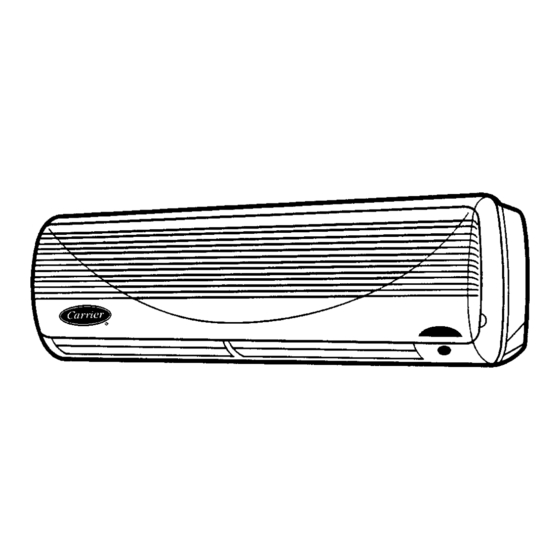
The new Carrier 40QNE heat pump high wall fan coil units
(Fig. 1) DO NOT have electric heaters. These new heat pump
fan coil units have been specifically designed to improve sys-
tem efficiency in both heating and cooling modes when matched
with a 38BK outdoor heat pump unit. If your application
requires heating, heat pump units must be used, both out-
doors and indoors. See Table 1 for recommended system
combinations.
Fig. 1 - 40QN High Wall Fan Coil Unit
Form 40QN-1SI
Pg 1
40QNB/QNE
018,024
4-96
Replaces: New
Advertisement
Table of Contents

Related Manuals for Carrier 38HDC018


Summary of Contents for Carrier 38HDC018
-
Page 1: Table Of Contents
Automatic Operation (Auto) Mode ... . 11 The new Carrier 40QNE heat pump high wall fan coil units Operating Fault Diagnosis ....11 (Fig. -
Page 2: Installation
40QN high wall fan coil unit. or winter start kit (HDS) that will allow operation down to −20 F. Check all items. If any item is missing notify your Carrier INSTALLATION distributor. To prevent loss or damage, leave all parts in origi- nal packages until installation. - Page 3 UNIT WEIGHT 40QN018 39 Lb (17.5 Kg) 40QN024 43 Lb (19.5 Kg) 1. Dimensions in ( ) are in millimeters. Direction of airflow. 3. Refrigerant, drain, and power connections may be made in unit rear, bot- tom, left side, or right side. 4.
-
Page 4: Step 3 − Mount Mounting Bracket On Wall
*A clearance of 4 is the absolute minimum. A clearance of 10 is recommended. NOTE: Remove unit front cover for control box access. Fig. 3 — Minimum Required Clearances *38HDC, 38BK/38HDS systems. Fig. 5 — Maximum Line Lengths Step 3 − Mount Mounting Bracket on Wall 1. -
Page 5: Step 4 - Connect Refrigerant Piping
Fig. 6 — Bracket Mounting If mounting bracket is not mounted level, the indoor sec- tion will be mounted unevenly, and condensate drain- age water may drip onto the floor. Also, a gap between the bracket and the wall may result in vibration and noise from the indoor section. - Page 6 NOTE: No AccuRater is required on 38HDS sys- tems. The 38HDS systems have a TXV (thermostatic expansion valve) in the condensing unit for refriger- ant metering and control. e. On heat pump installations, install factory-supplied pis- ton in the AccuRater metering device located in the service valve on the outdoor unit (Fig.
-
Page 7: Step 5 - Connect Condensate Drain Line
Step 5 — Connect Condensate Drain Line — Observe all local sanitary codes when installing condensate drains. Operation of unit on improper line voltage constitutes abuse and could affect warranty. Refer to Table 5 for 1. Connect drain line by inserting a ⁄... - Page 8 Table 5 — Electrical Data INDOOR MAX FUSE OPERATING VOLTAGE* V (Single- UNIT WATTS OR HACR TYPE Ph, 60 Hz) 40QN CKT BKR AMPS B018 B024 208/230 0.53 0.66 E018 E024 LEGEND — Full Load Amps HACR — Heating, Air Conditioning, and Refrigeration —...
-
Page 9: Step 7 − Make Connections To Outdoor Unit
Step 8 − Install Fan Coil Unit Onto Mounting Bracket 1. Hook the fan coil unit onto the top of the mounting bracket. See Fig. 16. 2. Snap the fan coil unit onto the mounting bracket as shown in Fig. 16. IMPORTANT: An audible snapping sound will be heard as the hook on the unit is secured into the hole on the mounting bracket. -
Page 10: 40Qn Control System
8. With the remote controller, turn on the unit and operate Adjusting Airflow — The airflow direction may be ad- in each mode (as applicable) for 15 minutes to test for justed up and down using the remote controller, and from proper operation. -
Page 11: Automatic Operation (Auto) Mode
Initial Operation — When the mode is first selected, one of Automatic Operation (Auto) Mode — If auto mode the following occurs: is selected, the system automatically switches the operating mode from heating (heat pump system only) to cooling, or 1. -
Page 12: Cleaning And Maintenance
Emergency operation settings are as follows: lights are installed nearby. The batteries may not need to be 1. Operation mode: AUTO. replaced. If you suspect this is the problem, consult your Carrier distributor. 2. Fan Speed: AUTO. Table 6 — Cleaning and Maintenance Schedule TASK... -
Page 13: To Set The Current Time
Replacement filters are available through your shows signs of disrupted operation if you use the wireless Carrier distributor. remote controller, or if the system is turned on or shows signs of disrupted operation when the remote controller of any other To Clean Indoor Unit Front Panel —... -
Page 14: To Clean Outdoor Coil (Outdoor Unit)
PRESS SET TIME PRESS Fig. 22 — Setting The Current Time REMOVE FILTER VACUUM CLEAN RINSE WITH WATER Fig. 23 — Air Filter Maintenance To access the LED indicator light, remove the front cover To Clean Outdoor Coil (Outdoor Unit) of the unit by removing the 3 screws holding it in place. -
Page 15: Compressor Failure
COMPRESSOR FAILURE System Safeties and Interlocks If the System is in Cooling or Dehumidification Mode — INDOOR FAN FAILURE — If the indoor fan rpm shows After 5 minutes of operation, if the temperature of the in- greater than 800 rpm for 30 seconds with the fan in the off door coil is not 4°... - Page 16 LEGEND AND NOTES FOR FIG. 24 AND 25 AGING — For the Burn-In Test — Outdoor Fan Motor (short terminals) — Outdoor Fan Relay — Assembly — Overload — Contactor — Printed Circuit Board — Capacitor RA TH — Return Air Thermistor —...
- Page 17 RELAY CHART COMPRESSOR THERMISTOR EQUIVALENCE TEMPERATURE RESISTANCE °F °C 6,500 11,400 32,500 ALL THERMISTORS IN THE 40QN SYSTEMS ARE IDENTICAL TO EACH OTHER Fig. 24 — Cooling-Only System (38HDC Shown)
- Page 18 Copyright 1996 Carrier Corporation Manufacturer reserves the right to discontinue, or change at any time, specifications or designs without notice and without incurring obligations. Book 1 4 PC 111 Catalog No. 534-078 Printed in U.S.A. Form 40QN-1SI Pg 18 4-96...
-
Page 19: Start-Up Checklist
†FIELD PIPING AND ALL TUBING CONNECTIONS MUST BE LEAK TESTED BY THE PRESSURE METHOD DE- SCRIBED IN CARRIER GENERAL TRAINING FOR AIR CONDITIONING MANUAL (GTAC2), MODULE 5. USE R-22 AT APPROXIMATELY 25 PSIG BACKED UP WITH AN INERT GAS TO REACH A TOTAL SYSTEM PRESSURE NOT TO EXCEED 245 PSIG. - Page 20 MEASURE AND RECORD THE: VAPOR LINE PRESSURE: PSIG DISCHARGE PRESSURE: PSIG Copyright 1996 Carrier Corporation Manufacturer reserves the right to discontinue, or change at any time, specifications or designs without notice and without incurring obligations. Book 1 4 PC 111 Catalog No. 534-078 Printed in U.S.A.
Need help?
Do you have a question about the 38HDC018 and is the answer not in the manual?
Questions and answers