Advertisement
CONTENTS
SAFETY CONSIDERATIONS . . . . . . . . . . . . . . . . . . . 1
INSTALLATION . . . . . . . . . . . . . . . . . . . . . . . . . . . . . . 1-6
Step 1 - Complete Pre-Installation
Checks . . . . . . . . . . . . . . . . . . . . . . . . . . . . . . . . . . . . 1
• UNPACK UNIT
• INSPECT SHIPMENT
• CONSIDER SYSTEM REQUIREMENTS
Step 2 - Rig and Mount Unit . . . . . . . . . . . . . . . . . 3
• MOUNTING ON GROUND
• MOUNTING ON ROOF
Connections . . . . . . . . . . . . . . . . . . . . . . . . . . . . . . . 3
• MAKE PIPING SWEAT CONNECTIONS
• PROVIDE SAFETY RELIEF
Step 4 - Make Electrical Connections . . . . . . . . 4
• CONTROL CIRCUIT WIRING
Step 5 - Accessory Installation . . . . . . . . . . . . . . 4
START-UP . . . . . . . . . . . . . . . . . . . . . . . . . . . . . . . . . . . 7
SERVICE . . . . . . . . . . . . . . . . . . . . . . . . . . . . . . . . . . . 7-9
MAINTENANCE . . . . . . . . . . . . . . . . . . . . . . . . . . . . . 10
TROUBLESHOOTING . . . . . . . . . . . . . . . . . . . . . . . . 11
SAFETY CONSIDERATIONS
Install and servicing air-conditioning equipment can be haz-
ardous due to system pressure and electrical components. Only
trained and qualified service personnel should install or serv-
ice air-conditioning equipment
Untrained personnel may perform basic maintenance such
as cleaning and replacing filters. All other operations should
be performed by trained service personnel. When working
on air-conditioning equipment, observe safety precautions in
literature, and on tags and labels attached to unit.
Follow all safety codes. Wear safety glasses and work
gloves. Use quenching cloth for brazing operations. Have a
fire extinguisher available. Read these instructions thor-
oughly. Consult local building codes and National Electrical
Code (NEC) for special installation requirements.
Manufacturer reserves the right to discontinue, or change at any time, specifications or designs without notice and without incurring obligations.
Book 1 4
PC 111
Tab
3a 2a
Light Commercial Condensing Units
Installation, Start-Up and
Service Instructions
Page
Catalog No. 563-885
Printed in U.S.A.
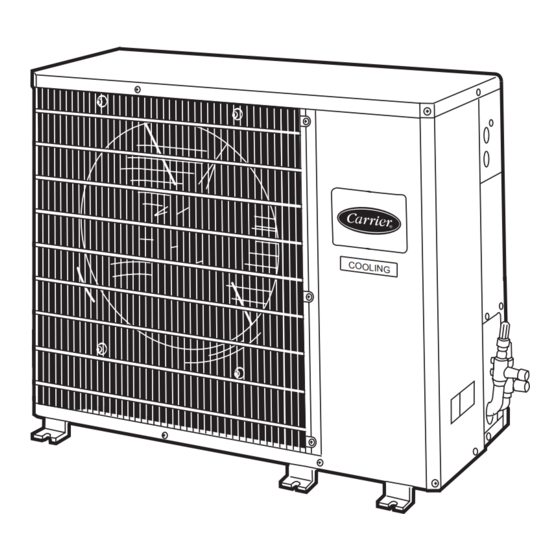
38HDL018-060
Fig. 1 - 38HDL Condensing Unit
INSTALLATION
Before installing or servicing system, always turn off
main power to system. There may be more than one dis-
connect switch. Turn off accessory heater power if
applicable. Electrical shock can cause personal injury.
Step 1 - Complete Pre-Installation Checks
UNPACK UNIT - Move unit to final location. Remove car-
ton from unit, being careful not to damage service valves or
grilles.
INSPECT SHIPMENT - File claim with shipping com-
pany if shipment is damaged or incomplete. Check unit name-
plate to ensure unit matches job requirements.
CONSIDER SYSTEM REQUIREMENTS - Consult
local building codes and NEC for special installation
requirements.
Allow sufficient space for airflow clearance, wiring,
refrigerant piping, and servicing unit. See Fig. 1 and 2. Unit
can be mounted on a level pad directly on base legs or
mounted on raised pads at support points. See Fig. 2 for cen-
ter of gravity.
Form 38HDL-2SI
Pg 1
CO O LI NG
1-99
Replaces: 38HDL-1SI
Advertisement
Table of Contents

Related Manuals for Carrier 38HDL018-060


Summary of Contents for Carrier 38HDL018-060
-
Page 1: Table Of Contents
Manufacturer reserves the right to discontinue, or change at any time, specifications or designs without notice and without incurring obligations. Book 1 4 PC 111 Catalog No. 563-885 3a 2a 38HDL018-060 Page Fig. 1 — 38HDL Condensing Unit INSTALLATION Before installing or servicing system, always turn off main power to system. - Page 2 NOTES: 1. Required clearances: With coil facing wall, allow 6 (156.4 mm) minimum clearance on coil side and 2. Dimensions in parenthesis are in millimeters. 3. Center of gravity Fig. 2 — 38HDL018-060 — Dimensional Drawing ft-in. ft-in. ft-in. ft-in.
-
Page 3: Step 2 - Rig And Mount Unit
When more than 50 ft of interconnecting tubing and more than 30 ft of vertical lift is used, refer to Part 3 of the Carrier System Design Manual for design details, or contact your local distributor. -
Page 4: Step 4 - Make Electrical Connections
75 ft, use no. 14 AWG insulated wire. NOTE: Operation of unit on improper line voltage consti- tutes abuse and could affect Carrier warranty. See Table 2. Do not install unit in system where voltage may fluctuate above or below permissible limits. -
Page 5: Outdoor Fan
UNIT 38HDL NOMINAL CAPACITY (Btuh) UNIT OPERATING WEIGHT (lb) COMPRESSOR Type Copeland Model ZR18KC-PFV Oil (oz) Initial/Recharge OUTDOOR FAN Diameter (in.)...No. of Blades Fan Pitch (Deg) Motor Hp Nominal Airflow (Cfm) OUTDOOR COIL Face Area (sq ft)...No. of Rows Fins per in. CONTROLS PRESSURESTAT SETTINGS Low Pressure... - Page 6 LEGEND — Contactor (12-va) — Heating Control — Indoor-Fan Motor — Indoor-Fan Relay TRANS — Transformer Field Wiring Factory Wiring Fig. 5 — Typical Control Circuit Connections *The IFR and IFM are located in indoor unit on heating-cooling applications. If accessory IFR is required for cooling-only applic- tions, locate (IFR) in fan coil.
-
Page 7: Start-Up
45 minutes to reset). When an internal overload is suspected of being open, check by using an ohm- meter or continuity tester. If necessary, refer to Carrier Stand- ard Systems Techniques Manual, Chapter 2, for complete information. - Page 8 OPERATIONAL UNIT SIZE V-PH-Hz 38HDL 208/230-1-60 LEGEND — Full Load Amps HACR — Heating, Air Conditioning, Refrigeration — Locked Rotor Amps — Minimum Circuit Amps per NEC Section 430-24 — National Electrical Code — Rated Load Amps (Compressor) *Permissible limits of the voltage range at which unit will operate satisfactorily.
- Page 9 SUBCOOLING METHOD (COOLING, TXV) — To check and adjust charge during cooling season, use Table 5 and the following procedure: 1. Operate unit a minimum of 15 minutes before checking charge. 2. Measure liquid line temperature near liquid line service valve, and measure liquid pressure at liquid line service valve.
-
Page 10: Maintenance
COMPRESSOR — Compressor contains factory oil charges; replace oil when lost. See Table 1 for oil recharge and refer to Carrier Standard Service Techniques Manual, Chapter 1, pages 1 to 21 for oil recharging procedure. See Table 6 for recommended compressor oils. - Page 11 TROUBLESHOOTING CHART — COOLING CYCLE...
- Page 12 Copyright 1999 Carrier Corporation Manufacturer reserves the right to discontinue, or change at any time, specifications or designs without notice and without incurring obligations. Book 1 4 PC 111 Catalog No. 563-885 Printed in U.S.A. Form 38HDL-2SI Pg 12 1-99...
Need help?
Do you have a question about the 38HDL018-060 and is the answer not in the manual?
Questions and answers