Carrier 38HDF018-036 Installation, Start-Up And Service Instructions Manual
Condensing units
Hide thumbs
Also See for 38HDF018-036:
Table of Contents
Advertisement
CONTENTS
SAFETY CONSIDERATIONS . . . . . . . . . . . . . . . . . . . . . . 1
Installation . . . . . . . . . . . . . . . . . . . . . . . . . . . . . . . . 1-10
Step 1 — Complete Pre-Installation Checks . . . . . . 1
• UNPACK UNIT
• INSPECT SHIPMENT
• CONSIDER SYSTEM REQUIREMENTS
• MATCHING THE CONDENSING UNIT TO AN
Step 2 — Rig and Mount Unit. . . . . . . . . . . . . . . . . . . . . 3
• MOUNTING ON GROUND
• MOUNTING ON ROOF
• RIGGING
Step 3 — Complete Refrigerant Piping
Connections . . . . . . . . . . . . . . . . . . . . . . . . . . . . . . . . . . . 3
• CHECK ACCURATER CONTROL
• FILTER DRIER
• MAKE PIPING SWEAT CONNECTORS
• PROVIDE SAFETY RELIEF
Step 4 — Make Electrical Connections . . . . . . . . . . . 6
• CONTROL CIRCUIT WIRING
• POWER WIRING
• CONNECTIONS TO DUCT-FREE FAN COIL UNITS
Start-Up . . . . . . . . . . . . . . . . . . . . . . . . . . . . . . . . . . . . . . . 11
Service . . . . . . . . . . . . . . . . . . . . . . . . . . . . . . . . . . . . . 11-14
Maintenance . . . . . . . . . . . . . . . . . . . . . . . . . . . . . . . . . 14
Troubleshooting. . . . . . . . . . . . . . . . . . . . . . . . . .14,15
SAFETY CONSIDERATIONS
Installing and servicing air conditioning equipment can be
hazardous due to system pressure and electrical components.
Only trained and qualified service personnel should install or
Service air conditioning equipment.
Untrained personnel can perform basic maintenance, such
as cleaning and replacing filters. All other operations should be
performed by trained service personnel. When working on air
conditioning equipment, observe safety precautions in litera-
ture, tags, and labels attached to unit.
Follow all safety codes. Wear safety glasses and work
gloves. Use quenching cloth for brazing operations. Have fire
extinguisher available. Read these instructions thoroughly.
Consult local building codes and the National Electrical Code
(NEC) for special installation requirements.
Before installing or servicing system, always turn off main
power to system. There may be more than one disconnect
switch. Turn off accessory heater power if applicable. Elec-
trical shock can cause serious personal injury.
Manufacturer reserves the right to discontinue, or change at any time, specifications or designs without notice and without incurring obligations.
Catalog No. 02-38HD0001-SI
Book 1
4
Tab
3e 2f
Installation, Start-Up and
Service Instructions
Page
Printed in U.S.A.
Duct Free Condensing Units
Ducted Condensing Units
Puron® (R-410A) refrigerant systems operate at higher
pressures than standard R-22 systems. Do not use R-22 ser-
vice equipment or components on Puron refrigerant equip-
ment. If service equipment is not rated for Puron refrigerant,
equipment damage or personal injury may result.
INSTALLATION
Step 1 — Complete Pre-Installation Checks
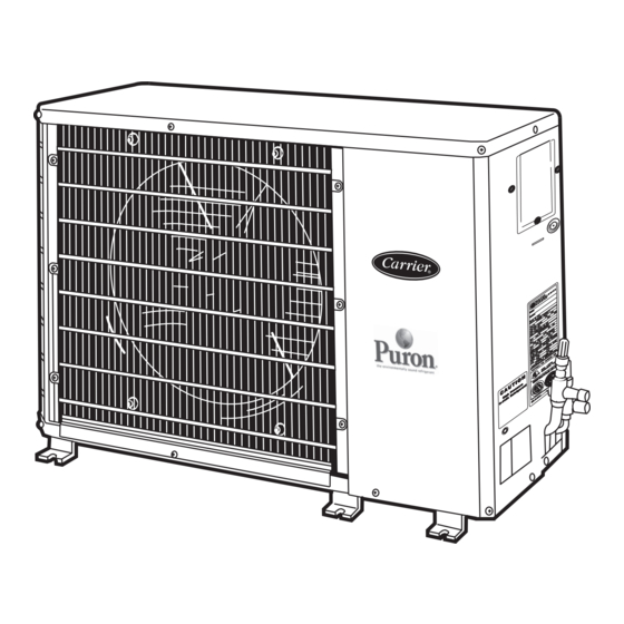
UNPACK UNIT (See Fig. 1) — Move the unit to final loca-
tion. Remove unit from carton, being careful not to damage
Service Valves and grilles.
Fig. 1 — 38HDF,HDR Unit
INSPECT SHIPMENT — File a claim with the shipping
company if shipment is damaged or incomplete. Check unit
nameplate to ensure unit matches job requirements.
CONSIDER SYSTEM REQUIREMENTS — Consult local
building codes and NEC for special installation requirements.
Allow sufficient space for airflow clearance, wiring, refrig-
erant piping, and servicing unit. See Fig. 2.
Locate unit so that condenser airflow is unrestricted on both
sides. Refer to Fig. 2.
Unit may be mounted on a level pad directly on base legs or
mounted on raised pads at support points. See Fig. 2 for center
of gravity.
MATCHING THE CONDENSING UNIT TO AN
INDOOR UNIT — The 38HDF,HDR units can be matched to
a corresponding indoor unit. The 38HDF018-036 units can be
matched with an in-ceiling cassette or high wall indoor unit.
The 38HDR unit can be matched with under-ceiling and resi-
dential fan coils. Refer to separate indoor unit literature for
more information.
Form 38HD-4SI
Pg 1
38HDF018-036
38HDR018-060
1-06
Replaces: 38HDC-3SI
Advertisement
Table of Contents
Troubleshooting

Related Manuals for Carrier 38HDF018-036


Summary of Contents for Carrier 38HDF018-036
- Page 1 MATCHING THE CONDENSING UNIT TO AN INDOOR UNIT — The 38HDF,HDR units can be matched to a corresponding indoor unit. The 38HDF018-036 units can be matched with an in-ceiling cassette or high wall indoor unit. The 38HDR unit can be matched with under-ceiling and resi- dential fan coils.
-
Page 3: Installation
See Fig. 4 for filter drier installation. NOTE: Arrow on AccuRater body points in free flow direction, away from the indoor coil. 38HDF018-036 38HDR018-060 Fig. 4 — AccuRater (Bypass Type) Metering Device Components... - Page 4 PROVIDE SAFETY RELIEF — A fusible plug is located in unit suction line; do not cap this plug. If local code requires additional safety devices, install as directed. Table 1A — 38HDF018-036 Physical Data AccuRater (Located at Fan Coil) 840/1720 840/1720 5.82...
- Page 5 UNIT 38HDR NOMINAL CAPACITY (Tons) OPERATING WEIGHT (lb) REFRIGERANT TYPE METERING DEVICE CHARGE (lb)* OUTDOOR FAN Rpm/Cfm Diameter (in.) No. Blades Motor (hp) OUTDOOR COIL Face Area (sq ft) No. Rows HIGH PRESSURE SWITCH Cut-In (psig) Cutout (psig) LOW PRESSURE SWITCH Cut-In (psig) Cutout (psig) REFRIGERANT LINES...
-
Page 6: Step 4 — Make Electrical Connections
NOTE: All wiring must conform to NEC and local codes. NOTE: Operating unit on improper line voltage constitutes abuse and could affect Carrier warranty. See Tables 2 and 3. Do not install unit in a system where voltage may fluctuate above or below permissible limits. - Page 7 VOLTAGE RANGE* 38HDF V-PH-Hz UNIT SIZE 208/230-1-60 208/230-1-60 208/230-1-60 208/230-1-60 208/230-3-60 460-3-60 LEGEND — Full Load Amps HACR — Heating, Air Conditioning, Refrigeration — Locked Rotor Amps — National Electrical Code — Rated Load Amps (Compressor) *Permissible limits of the voltage range at which unit will operate satisfactorily.
- Page 8 VOLTAGE RANGE* 38HDR V-PH-Hz UNIT SIZE 208/230-1-60 208/230-1-60 208/230-1-60 208/230-1-60 208/230-3-60 460-3-60 208/230-1-60 208/230-3-60 460-3-60 208/230-1-60 208/230-3-60 460-3-60 LEGEND — Full Load Amps HACR — Heating, Air Conditioning, Refrigeration — Locked Rotor Amps — National Electrical Code — Rated Load Amps (Compressor) *Permissible limits of the voltage range at which unit will operate satisfactorily.
-
Page 11: Start-Up
START-UP Preliminary Checks 1. Check that all internal wiring connections are tight and that all barriers, covers, and panels are in place. 2. Field electrical power source must agree with unit name- plate rating. 3. All service valves must be open. 4. - Page 12 To troubleshoot: 1. Apply voltmeter across crankcase heater leads to see if heater voltage is on. Do not touch heater. Carefully feel area around crankcase heater; if warm, crankcase heater is functioning. 2. With power off and heater leads disconnected, check across leads with ohmmeter.
- Page 13 Table 4 — Pressure vs. Temperature Chart — Puron® Refrigerant (R-410A) PRESSURE TEMPERATURE PRESSURE TEMPERATURE PSIG °F PSIG °F –37.7 37.8 –34.7 38.7 –32.0 39.5 –29.4 40.5 –26.9 41.3 –24.5 42.2 –22.2 43.0 –20.0 43.8 –17.9 44.7 –15.8 45.5 –13.8 46.3 –11.9 47.1...
-
Page 14: Service
Table 5 — Subcooling Charging Table REQUIRED LIQUID LINE TEMPERATURE (F) LIQUID PRESSURE AT SERVICE VALVE Required Subcooling (psig) Temperature (F) Compressor Lockout Switch — are provided with a compressor lockout protective device. If the compressor shuts down due to any safety device, a current loop monitoring the compressor current senses no current flow. -
Page 15: Troubleshooting
Fig. 9 — Troubleshooting the Cooling Cycle... - Page 16 Copyright 2006 Carrier Corporation Manufacturer reserves the right to discontinue, or change at any time, specifications or designs without notice and without incurring obligations. Catalog No. 02-38HD0001-SI Printed in U.S.A. Form 38HD-4SI Pg 16 2-06A 1-06 Replaces: 38HDC-3SI Book 1...
Need help?
Do you have a question about the 38HDF018-036 and is the answer not in the manual?
Questions and answers