
Related Manuals for Torbal ATA Series


Summary of Contents for Torbal ATA Series
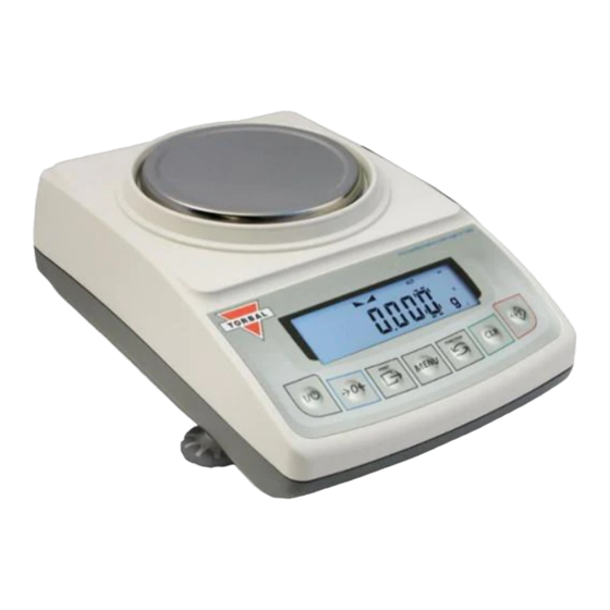
- Page 1 Instruction Manual: ATA Series Models: ATA220, ATA220i, ATA320, ATA320i, ATA520i, ATA1200, ATA1200i, ATA2200, ATA2200i...
-
Page 2: Table Of Contents
Table of Contents Chapter 1: Cautionary Notes and Warnings ........................... 1 Chapter 2: Specifications ................................ 3 Chapter 3: Parts Description .............................. 4 Chapter 4: Keys, Display Indicators and Commands ....................... 6 Chapter 5: Unpacking the Scale and Getting Started ...................... 8 Chapter 6: Main Menu ................................. 10 Chapter 7: Calibration (CALIBR) ............................ 11 7.1 Calibration ‐ Automatic Internal .......................... 11 7.2 Calibration ‐ External .............................. 12 7.3 Calibration – External (NTEP Certified Legal for Trade Models) ................. 13 Chapter 8: Units of Measure Selection (UNIT) ........................ 15 Chapter 9: Mode Configuration (MMODE) .......................... 16 9.1 Animal Weighing Configuration .......................... 17 9.2 Parts Counting Configuration ............................ 19 9.3 Check Weighing Configuration ............................ 20 9.4 Display Hold Configuration ............................ 21 9.5 Percent Weighing Configuration .......................... 22 9.6 Totalizing Configuration .............................. 23 Chapter 10: Auto Zero Setting Mechanism – AZSM (AUTO) .................... 25 Chapter 11: GLP Print and Data Configuration (GLP) ...................... 26 Chapter 12: Printing Data and Communication Ports (PORTS) ..................... 29 12.1 Baud Rate .................................. 29 12.2 Bits ..................................... 30 12.3 Parity .................................. 30 ... -
Page 3: Chapter 1: Cautionary Notes And Warnings
Instruction Manual – ATA Series Chapter 1: Cautionary Notes and Warnings Important handling Cautions and Warnings Always handle your scale with care. Damage caused by improper handling is not covered under the scale’s warranty. Never drop or throw any articles onto the scale’s pan... - Page 4 nstruction Man nual – ATA Ser ries CAUT TIONAR RY NOT TES AND D PREC CAUTIO Alwa ays handle yo our scale with h care. The co orrect location n and proper environment t makes an im mportant contr ribution to th accur racy of the w...
-
Page 5: Chapter 2: Specifications
Instruction Manual – ATA Series Chapter 2: Specifications Model ATA220 ATA320 ATA520 ATA1200 ATA2200 Capacity 220 g 320 g 520 g 1200g 2200g Readability (d) 0.001 g 0.01g Verification (e) 0.01 g 0.1g Repeatability (Standard Deviation) 0.001g 0.01g Linearity +/‐ 0.002g +/‐ 0.02g Tare Range ‐220 g ‐320 g ‐520 g ‐1200g ‐2200g ... - Page 6 nstruction Man nual – ATA Ser ries hapter 3: : Parts D Descriptio ont Side Rear Pan Pan Support Draft Ring AC Ad dapter Leve ling Feet Bubble e Level Ind icator AC Adapte er Socket | Service Sw witch Acce ess | RS232 2 Port | US...
- Page 7 Instruction Manual – ATA Series 5 ...
- Page 8 nstruction Man nual – ATA Ser ries hapter 4: : Keys, D Display In ndicators s and Com mmands Key Primary y Function Secondary F Function Powe r On/Off ‐ Enter and YE ES (Accept) – U Used to enter o or accept re – used to tar re the weighin g pan comma ands No (Reject) –...
- Page 9 nstruction Man nual – ATA Ser ries Main n Menu Indi icates Main Me enu Functions . MODE The weighing g result has sta abilized and an n accurate Stability y Indicator reading may be taken. In check weig ghing MIN indi icates that the weighing nimum result is s below the se lected under li imit. In check weig ghing MAX ind icates that the e weighing ximum result i is above the se elected over lim mit. ...
-
Page 10: Chapter 5: Unpacking The Scale And Getting Started
Instruction Manual – ATA Series Chapter 5: Unpacking the Scale and Getting Started 1. Carefully remove the scale, pan, and all of its components out of the packaging. Place them on a stable surface where the scale will not be affected by any mechanical vibrations or high air movements. 2. After removing the pan base and the pan from their packaging, carefully install the pan base (2) onto the scale by seating it on the pan support located in the middle of the scale. Once the pan base has been installed, carefully place the pan (1) on the base 3. Once the pan has been installed, level the scale by adjusting the front feet (6) until the level indicator (7) shows the “air bubble” is in the center position of the sight glass. The level indicator is located on the rear left side of the scale. 1 – pan 2 – pan support (under pan) 3 – draft ring 4 – display LCD 5 – keys 6 – rotating legs 7 – level indicator 8 – draft shield (option) 9 – draft shield cover (option) Correct Incorrect 4. After leveling the scale, you may plug the AC adaptor to the AC adaptor socket located in the rear of the scale. ... - Page 11 Instruction Manual – ATA Series 5. When the AC adaptor is plugged into the wall outlet, the scale will automatically turn on, and go through its initialization process. Note – For Scales w/ Automatic Internal Calibration: When the AC adapter is plugged into the wall outlet for the first time, the scale will automatically and frequently initialize temperature calibration as the internal parts of the scale heat up. The scale will display “WWAIT” when calibrating. Once the internal temperature stabilizes, the scale will calibrate whenever the temperature changes by 1 degree Celsius and at two‐hour intervals. The scale loses internal temperature only when the unit is completely unplugged from the wall electrical outlet. When the unit is turned off with the On/Off key, the scale goes into standby mode and internal temperature is maintained. WWAIT 6. To put the scale into standby mode, leave the AC adaptor plugged into both the scale and the wall outlet and press the Power “OFF” button. The “OFF” indicator will light up in the upper left corner of the display signaling the scale is in standby mode. 9 ...
-
Page 12: Chapter 6: Main Menu
nstruction Man nual – ATA Ser ries hapter 6: : Main M Menu The M Main Menu is s used to conf figure the sca ale and its we eighing modes s. There are nine options within the M Main Menu: CALIB UNIT MODE Ports AUTO), GLP (G GLP), Ports ( /Date (SET T TD) and Reset Calib bration ( ), Unit ( ), Mode ( ), AZSM ( ), Time/ t ... - Page 13 nstruction Man nual – ATA Ser ries LIBR) hapter 7: : Calibra ation (CAL Not L Legal for Trade m models only 7.1 C Calibration ‐ Automat tic Internal: : Auto omatic Interna al Calibration Models: calib bration is aut tomatically pe erformed eve ery time the s scale is turned d ON or initia alized. Calibra ation is also pe erformed eve ery time the i...
-
Page 14: Calibration - External
nstruction Man nual – ATA Ser ries 7.2 C Calibration – External : Exter rnal calibratio on can be per rformed with an external c calibration we eight equal to o the scale’s c capacity. Calib” by pr 1. T To start calibr ration, press t the “MENU” k key. Select “C ressing the “T T” key. Select “CAL s start” by pre 2. S essing the “T” ” key. The sc ale will then b begin to perf... - Page 15 nstruction Man nual – ATA Ser ries 7.3 C Calibration – External (NTEP Cert tified Legal l for Trade Models On nly): Exter rnal calibratio on can be per rformed with an external c calibration we eight equal to o the scale’s c capacity. WWeIgH" 6. E Enter the Wei ighing Mode by pressing t he Function k key. Select “ by p pressing the “ “T” key. WWEI 7.
- Page 16 nstruction Man nual – ATA Ser ries 12. W Wait for the s scale to tare. -CAL 13. W When prompt ted, load a ca alibration wei ght equal to t the weight di isplayed on th he screen. (Ca a libration we e ight varies by y model). 14. W Wait for the s scale to calibr ate. ...
- Page 17 nstruction Man nual – ATA Ser ries hapter 8: : Units of f Measur re Selecti ion (UNIT Not Legal for r Trade models o TORB BAL ATA serie es scales can o operate in nin ne different u units of meas ure: grams (g g), kilograms ( (kg), carats (c ct), pounds (lb), N Newton (N), g grains (gn), o unces (oz), ou unces troy (o z‐t), and penn nyweights (dw...
- Page 18 nstruction Man nual – ATA Ser ries MODE) hapter 9: : Mode C Configura ation (MM Not Le egal for Trade mo odels only TORB BAL ATA serie es scales can o operate in six x application m modes: Anim mal Weighing ( (ANIMMAL), P arts Counting g (PARTS), CHECK), Displ PLAY), Perce Chec ck Weighing (C lay Hold (DIS ent Weighing ...
- Page 19 nstruction Man nual – ATA Ser ries 9.1 A Animal We eighing Con figuration Anim mal weighing i s used to we igh live anima als and other dynamic load ds. A choice o of 3 different operating mo odes and 4 diffe rent weight in ntegration pe eriods ensure s the user the e best results s in the least a amount of tim me per measu urement. MMAL” in the 1. T To enable Ani mal Weighing g, select “ANI e Mode Menu u by pressing “T” (YES) key y. ...
- Page 20 Instruction Manual – ATA Series DONE î 5. After selecting the time interval, “ ” will be displayed, indicating that the function has been configured and it is ready to use. DONE To use the function, follow the directions given in Chapter 16. To exit the mode menu press the “CLR” key. Table 9.1: Animal Weighing Operating Modes Automatic Weighing Initialization: Automatic When set to Automatic, the scale will automatically begin the animal weighing process. Once the animal is Result Clearing: Automatic removed from the weighing pan, the scale will Tare: Automatic automatically tare and prepare for the next weighing. Semi‐Automatic Weighing Initialization: Automatic When set to Semi‐Automatic, the scale will automatically begin the animal weighing process. Result Clearing: Manual Once the animal is removed from the weighing and ...
- Page 21 nstruction Man nual – ATA Ser ries 9.2 P Parts Count ting Config guration Parts s Counting is u used to count t a batch of it tems based o n their weigh ht. A sample is taken to de etermine the average piece e weight of th he items. S” in the Mod 1. T To enable Par rts Counting, select “PARTS de Menu by p pressing “T” ( YES) key. ARTS Co On” and “C Co OFF” will ...
- Page 22 nstruction Man nual – ATA Ser ries Note e: Larger samp ple size result ts in a more a accurate aver age piece we eight. Select a a sample size greater than 10 pieces if a a large e weight varia ance might ex xist between t the counted p pieces. DONE î 4. A After selecting g the sample size, “ ” will be displ ayed, indicat ing that the f function has b been configur red and it is ready to use. ...
-
Page 23: Display Hold Configuration
nstruction Man nual – ATA Ser ries DONE 4. T To use the fun nction follow the direction ns in Chapter 18. To exit th he mode men nu use the “CL LR” key. 4 9.4 D Display Hol ld Configur ration 23 Displ lay Hold is use ed to lock a w weight readin g on the scre en, even afte er the weighe ed object has been remove ed from the pan. ... - Page 24 nstruction Man nual – ATA Ser ries î 4. A After selecting g the operati ng mode, “ ” will be d displayed, ind dicating that the function has been con nfigured and t is ready to u use. DONE 5. T To use the fun nction follow the direction ns in Chapter 19. To exit th he mode men nu use the “CL LR” key. 4 Tabl le 9.4: Displa ay Hold Ope...
-
Page 25: Totalizing Configuration
nstruction Man nual – ATA Ser ries E OFF E ON DONE î 3. A After enabling g Percent We eighing, “ ” will be dis splayed, indic cating that the e function ha s been config gured and it is s ready to use. DONE 4. T To use the fun nction follow ... - Page 26 Instruction Manual – ATA Series DONE î 4. After selecting the operating mode, “ ” will be displayed, indicating that the function has been configured and it is ready to use. DONE 5. To use the function follow the directions in Chapter 21. To exit the mode menu use the “CLR” key. 24 Table 9.6: Totalizing Operating Modes Automatic Totalizing and Adding: Automatic When set to Automatic, the scale will automatically add the first stable weight reading to the total. Manual Totalizing and Adding: Manual When set to Manual each weigh has to be manually added to the total by pressing a designated key. 24 ...
- Page 27 nstruction Man nual – ATA Ser ries hapter 1 0: Auto Z Zero Sett ting Mec chanism – – AZSM (AUTO) All AT TA scales are equipped wi th AZSM, the e “Auto Zero S Setting Mech anism.” AZSM M automatica ally maintains s a “center of zero” ” condition w within +/‐ 6d (i i.e. 6 mg on s scales with 0.0 001g readabi lity). ...
-
Page 28: Chapter 11: Glp Print And Data Configuration (Glp)
Instruction Manual – ATA Series Chapter 11: GLP Print and Data Configuration (GLP) When enabled, GLP data will appear on every printed transaction receipt. The GLP printout includes Unit ID (UNIT ID), User ID (USER ID), Project No. (PROJECT), Notes / Remarks field, and a Signature field. UNIT ID USER ID PROJECT Example of printout: 26 ... - Page 29 nstruction Man nual – ATA Ser ries To en nable and con nfigure GLP d ata printing, follow the ste eps below. 1. P Press the “ME ENU” key. Se lect “GLP” by y pressing the e “T” (YES) key y. 2. S Select “SET” b by pressing th he “T” (YES) ke ey. 3.
- Page 30 nstruction Man nual – ATA Ser ries 6. P Press the “ to increment t a digit. Pres ss the “T” (YE ES) to accept a and add a dig git. 0 ” key ( 7. P Press the “FU NCTION” key y to accept the e entire settin ng. Press the e “CLR” key to o clear and st art over. ...
-
Page 31: Baud Rate
nstruction Man nual – ATA Ser ries hapter 12 2: Printin ng Data a and Com mmunicat tion Port ts (PORTS After r a weighing o or counting tr ransaction is c completed, a result data r receipt can be e printed. To initiate printi ing, press the data transfer key. Data may be e sent to a pri nter or a PC v via the Torba l Communica ation Softwar e. ... -
Page 32: Bits
nstruction Man nual – ATA Ser ries 0”, “2400”, “ 0”, “19200”, 7600”, and “ 2. C Choose the ba aud rate to be e used (“1200 “4800”, “9600 “38400”, “5 “115200”). To confirm th e selection, p press the “T” key. Exam mple (Selectin ng 9600): 9600 12.2 2 Bits 1. T To configure t the number o of bits select “... - Page 33 nstruction Man nual – ATA Ser ries 12.4 4 Send – Se nding Data a to PC or P rinter enf” by press 1. T To configure t the data send ding format ty ype select “Se sing the “T” k key. Send oStab”, “AUT O”,“REMOVE" " and “even” 2. C Choose the da ata sanding fo ormat (“off” ”, “Stab”,“no ”). To confirm m the ...
-
Page 34: 12.5 Installing Drivers
Instruction Manual – ATA Series 12.5 Installing Drivers Before connecting the scale to a computer the USB Port must be configured with the appropriate baud rate and other necessary parameters. To configure the USB Port, follow configuration steps from this chapter and apply them to the USB settings. PC Connection via USB Once the USB port has been configured, connect the scale to the PC with a Standard A/B USB cable and follow the “Found New Hardware” configuration wizard as described below. 1. Allow Windows to connect to Windows Update in order to search for software. Select “Yes, this time only” and click “Next”. Once driver “FT232R USB UART” has been found, select “Install the software automatically (Recommended)” and click “Next. 32 ... -
Page 35: Data Transmission And Exchange Protocol
Instruction Manual – ATA Series 2. Windows will begin installation of the driver, when completed click “Finish”. 3. Once installation of the driver has been completed the scale is ready to communicate with the PC via the USB port. 12.6 Data Transmission and Exchange Protocol Data Transmission (LONG): Transmission Parameters: 8 bits, 1 stop bit, no parity, baud rate 4800bps, Exchange data: Transmit the weight (equivalent to the Print Key, , in weighing: Computer→Scale: S I CR LF (53h 49h 0Dh 0Ah) – initiating signal, Scale→Computer: scale sends 16 Bytes of data as follows: Byte 1 ‐ The charater ‘‐‘ or space Byte 2 ‐ space Bytes 3,4 ‐ digit or space ... - Page 36 Instruction Manual – ATA Series ‘Tare the weight’ (corresponds to the →T← key in weighing): Computer→Scale: S T CR LF (53h 54h 0Dh 0Ah), Scale→Computer: no response. ‘Zero the scale’ (corresponds to the key →0← in weighing): Computer→Scale: S Z CR LF (53h 5Ah 0Dh 0Ah), Scale→Computer: no reponse. ‘Turn On / Off the Scale (corresponds to the key I/ in weighing): Computer→Scale: S S CR LF (53h 53h 0Dh 0Ah), Scale→Computer: no response. ‘Display the MENU’ (corresponds to the key MENU in weighing): Computer→Scale: S F CR LF (53h 46h 0Dh 0Ah), Scale→Computer: no response. Setting the threshold 1 (optional): Computer→Scale: S L D1...DN CR LF (53h 4Ch D1...DN 0Dh 0Ah) where: D1...DN – Threshold value, up to 8 characters, Scale→Computer: no response, Example: To set 1000g in weight B1.5 (d=0.5g) type: S L 1 0 0 0 . 0 CR LF (53h 4Ch 31h 30h 30h 30h 2Eh 30h 0Dh 0Ah). To set 100kg in weight B150 (d=50g) type: S L 1 0 0 . 0 0 CR LF (53h 4Ch 31h 30h 30h 2Eh 30h 30h 0Dh 0Ah), Setting the threshold 2 (optional): Computer→Scale: S H D1...DN CR LF (53h 48h D1...DN 0Dh 0Ah), where: D1...DN – threshold value, up to 8 characters, Scale→Computer: no response ...
-
Page 37: Time
nstruction Man nual – ATA Ser ries SET TD) hapter 13 3: Time & & Date (S To se et the current t time and da te, follow the e steps below w. 13.1 1 Time lect “SET TD D” by pressing 1. P Press the “ME ENU” key. Se g the “T” key. ET T ... -
Page 38: Date
nstruction Man nual – ATA Ser ries 13.2 2 Date lect “SET TD D” by pressing 1. P Press the “ME ENU” key. Se g the “T” key. ET T 2. S Select “DATE” ” by pressing t the T key. DATE 3. T The current d ate will be di splayed. To c hange the da... - Page 39 nstruction Man nual – ATA Ser ries hapter 14 4: Restor ring Defa ault Facto ory Setti ings (RES The R Reset functio n resets all m modes and app plications as w well as restor res default fa ctory settings s. To restore default facto ory settings fo ollow the step ps below. 1. P Press the “ME ENU” key. Se lect “RESET” by pressing t the “T” key.
-
Page 40: Chapter 15: Weighing (Wweigh)
nstruction Man nual – ATA Ser ries IGH) hapter 15 5: Weigh hing (WWE WWeIgH gH" 1. T To enter Weig ghing Mode, press the Fun nction key. Se elect “ by pressin ng the T key. WWEI 2. W Wait for the s stabilization in ndicator to ap ppear. ... -
Page 41: Taring The Scale
nstruction Man nual – ATA Ser ries 3. R Re‐zero the sc cale by pressi ng the zeroin ng key. ---- ---- 4. W When finished d re‐zeroing, the scale will return to We eighing Mode e and the disp play will indic cate “0”. A ne ew center of zero has been n set, and the scale is ready y for weighin g. 0.000 Note e: Re‐zeroing g the scale wi... -
Page 42: Clearing The Tare
nstruction Man nual – ATA Ser ries 4. W When finished d taring, the b balance will r return to Wei ghing Mode. The display w will indicate “ “0”, and the N NET indicator will be shown on the displa ay signaling t he next weigh ht taken is a N NET result. 0.000 Note e: Do not tou uch or move t the scale duri ing the taring g process. 15.3 3 Clearing t the Tare ... - Page 43 nstruction Man nual – ATA Ser ries MMAL) hapter 16 6: Anima al Weigh ing (ANIM Anim mal weighing i s used to we igh live anima als and other dynamic load ds. A choice o of 3 different operating mo odes and 4 diffe rent weight in ntegration pe eriods ensure s the user the e best results s in the least a amount of tim me per measu urement. An “A” i ndicator will appear on th e screen to in ndicate the sc cale is in Perc...
- Page 44 nstruction Man nual – ATA Ser ries ual: n set to manu ual, animal w weighing must t be initialized d manually by y pressing the e “FUNCTION ” key. 4. O Once the anim mal weighing process is ini tialized, the s scale will disp play the time inter rval that was selected in th he configurat ion mode and d begin countin g down. Dur ring the time interval the s scale will reco ord ...
- Page 45 nstruction Man nual – ATA Ser ries Semi i‐Automatic a and Manual: n set to Semi ‐Automatic o or Manual, the e weighing re esult will rem ain displayed d and it must be manually cleared after the a animal has be een removed. To clear the weighing res ult, press the e “C” key. Aft ter the result has been cle ared, tare the e scale e by pressing t the “T” key. ---- ...
- Page 46 nstruction Man nual – ATA Ser ries hapter 17 7: Parts C Counting g (PARTS) Parts s Counting is u used to count t a batch of it tems based o n their weigh ht. A sample is taken to de etermine the average piece e weight of th he items. A “B B” indicator w will appear on the screen to o indicate the e scale is in P arts Counting g mode. 1. T To enter Parts s Counting M ode, press th he “Function”...
- Page 47 nstruction Man nual – ATA Ser ries ad “SAPL ON. 4. A After confirm ing the samp le size, the di splay will rea ” Place the sam mple into the w weighing con tainer. PL ON Note e: Minimum in ndividual piec ce weight mu ust be equal to o or greater than 3e. Attempti ing to set an a average indiv vidual piece w weight which i is rror (SAPL LO O). To see this lowe...
- Page 48 Instruction Manual – ATA Series 8. Once an accurate piece count has been taken, the container and its contents may be removed from the scale. 9. After the container with the counted pieces has been removed, COUNT FINISH TO START COUNT PRESS C the command “‐‐‐, , ” will appear on the display sequentially. Press the “CLR” key to begin a new count. ------ COUNT FINISH COUNT PRESS C START ...
- Page 49 nstruction Man nual – ATA Ser ries hapter 18 8: Check k Weighin ng (CHEC The c check weighin ng function is s used to com mpare the wei ght of an obje ect against a preset target t range. To se et the limits and u use the check k weighing fun nction follow w the steps be low. A “C” in ndicator will a appear on the e screen to in dicate the scale e is in Check W Weighing mod de. ...
- Page 50 nstruction Man nual – ATA Ser ries Table e 18.1; Exam ple: Setting a a weight limit t of 20.123g urrent display Action to take e ey to use Number of d depressions Display y becomes ‐ Increme ent the digit 3 2 (No) 2 Accept a and go to nex xt digit T ( Yes) 1 20 20 Insert a decimal int ...
- Page 51 Instruction Manual – ATA Series 5. The scale is now ready to use. To perform check weighing place your object on the pan to check whether the weight of the object falls within the designated range. If the weight is less than the lower limit the scale will display the weight of the object and the command “UNDER”. If the weight falls within the range, the “ACCEPT” command will be displayed. If the weight exceeds the upper limit, the scale will display “OVER”. UNDER ACCEPT OVER 54 Note: To change the limit setting press “CLR” and repeat Steps 1 to 7. If the same limits are used, the scale can be tared without clearing the function and the new object can be weight‐checked. 6. To exit Check Weighing, press the “CLR” key to clear the function. 49 ...
- Page 52 nstruction Man nual – ATA Ser ries DISPLAY hapter 19 9: Displa ay Hold (D Displ lay Hold is use ed to lock a w weight readin g on the scre en, even afte er the weighe ed object has been remove ed from the pan. A “D” indica tor will appea ar on the scre een to indicat te the scale is s in Display Ho old mode. isplay” by p 1. T To enter Disp lay Hold Mod de, press the “...
- Page 53 nstruction Man nual – ATA Ser ries ual: n set to Man ual, press the e “FUNCTION” ” key to lock t the result on th he screen. 100.0 4. C Clearing the d display Auto omatic: n set to Auto matic, the sc ale will autom matically clea r the result fr rom the scree en when the w weight is rem moved from the c container. Th e scale will p erform an au tomatic tare ...
- Page 54 nstruction Man nual – ATA Ser ries cent) hapter 20 0: Percen nt Weigh hing (Per Perce ent Weighing g is used to co ompare the re elative weight t of an unkno own item to t hat of a previ iously stored sample. An “E” in ndicator will a appear on the e screen to in ndicate the sc cale is in Perce ent Weighing g mode. 1. T To enter Perc ent Weighing g Mode, press s the “Functio...
- Page 55 nstruction Man nual – ATA Ser ries To ch hange the sam mple weight, place a new s sample in the e weighing SAPL ON” is d conta ainer when “S displayed. On nce stabilized d, press the “T” (Y Yes) key to ac ccept the new w weight. PL ON 100.0 Note e: The referen nce sample m ust be equal to or greater than 100d. ...
- Page 56 Instruction Manual – ATA Series Note: To change the initial sample press “CLR” and repeat Steps 1 to 3. If the same sample weight is used, the scale can be tared without clearing the function and new objects can be weighed. 6. To exit Percent Weighing, press the “CLR” key. 54 ...
- Page 57 nstruction Man nual – ATA Ser ries TAL) hapter 21 1: Totaliz zing (TOT Total lizing is used to calculate t the summatio on of multiple e weights that t are recorde ed sequentiall ly. An “F” ind dicator will appe ear on the scr een to indica te the scale is s in Totalizing g Mode. AL” by pressin 1. T To enter Tota lizing Mode, press the “Fu unction” key. Select “TOTA ng the “T” ke y. ...
- Page 58 nstruction Man nual – ATA Ser ries ual: n set to Man ual, press the e “FUNCTION” ” key to add t the weight to o the total. A TOTAL indica ator will appe e ar on the displ ay. Note e: With each added weigh t, the grand t total result w ill appear on th he display for approximate ely three seco onds. To reca all the grand total at any time, press the “M MENU” key. ...
-
Page 59: Chapter 22: Sealing The Calibration Switch
Instruction Manual – ATA Series Chapter 22: Sealing the Calibration Switch (Legal for Trade models only) Depending on individual state law, the calibration feature of the scale may be required to be sealed by an NIST/NTEP official. To seal the calibration feature, follow the instructions below. The scale can be sealed in two ways by using either a paper seal or a wire seal. Paper Seal: 1. To seal the scale using a paper seal or a sticker, use a flathead screwdriver to gently remove the calibration wire seal screw located in the rear of the scale. 2. Once the wire seal screw has been removed and the calibration switch exposed, gently insert the flush sealing screw provided with the scale in the place of the wire seal screw. Warning: Do not attempt to screw the flush sealing screw all the way in. Stop when the screw is flush with the casing of the scale. ... -
Page 60: Chapter 23: Common Errors And Trouble Shooting
Instruction Manual – ATA Series Chapter 23: Common Errors and Trouble Shooting Error or Indicator Cause Explanation / Solution ‐ ‐ ‐ ‐ Below Zero Re‐zero the scale by pressing the “ 0 “ key. ‐ ‐ Taring is not allowed Place a weight on the pan before taking a tare. ‐ ‐ Re‐zeroing is not allowed Remove weight from the pan and clear stored tare values L Pan error Make sure the pan is properly seated on the pan support. H Exceeded capacity The scale has exceeded its weighing capacity. Reduce the weight. Err – b Pan not cleared on power‐up ... -
Page 61: Chapter 24: Maintenance
Instruction Manual – ATA Series Chapter 24: Maintenance Cleaning and maintaining your Prescription Scale: • Before cleaning the scale always unplug the A/C adapter from the electrical outlet. • Use a soft, slightly damp cloth to clean the exterior housing of your scale. -
Page 62: Chapter 25: Accessories
Instruction Manual – ATA Series Chapter 25: Accessories Description Part No. Draft Shield Cover (Select Models Only) 301086 Dust Cover 301056 RXP-4 Thermal Printer 301060 RS232 PC Cable 301058 60 ... -
Page 63: Chapter 26: Replacement Parts
Instruction Manual – ATA Series Chapter 26: Replacement Parts Description Part No. A/C Adaptor 301054 Pan (115mm) 501094 Pan Base 501095 RS232 Printer Cable 61 ... -
Page 64: Chapter 27: Limited Warranty
Instruction Manual – ATA Series Chapter 27: Limited Warranty PURCHASER’S WARRANTY Warranty is valid only if your product has been registers within 30 days of receipt This product is a precision device made to exacting standards of scientific accuracy. It is guaranteed to have been adjusted and inspected for proper workmanship and performance, and certified for its currently advertised specifications before shipment. Scientific Industries’ Products are warranted against defects in material and workmanship under normal use and service. - Page 65 Scientific Industries, Inc. 80 Orville Dr. Bohemia, NY 11716 Tel. (973)473-6900 Fax. (973)777-8302 www.torbalscales.com...
Need help?
Do you have a question about the ATA Series and is the answer not in the manual?
Questions and answers