
Related Manuals for ADIATEK ruby Series


Summary of Contents for ADIATEK ruby Series
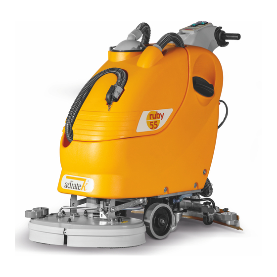
- Page 1 ruby 06 2018 Use and maintenance Warning! Please read the instructions before use.
-
Page 3: Table Of Contents
INTRODUCTORY COMMENT Thank you for having chosen our machine. This floor cleaning machine is used for the industrial and civil cleaning and is able to clean any type of floor. During its advance movement, the combined action of the brush and the detergent solution removes the dirt which is aspirated through the rear suction assembly, giving a perfectly dry surface. -
Page 4: Technical Description
TECHNICAL DESCRIPTION ruby 45 light ruby 55 light ruby 48bl ruby 48blt Cleaning width Squeegee width 1575 1925 1700 1700 Working capacity, up to sqft/h 16.954 20.722 18.300 18.300 2x235 2x285 1 x 485 1 x 508 Brushes diameter 2x11 1 x 19 1 x 20 Brushes rpm... - Page 5 ruby 48 bh ruby 45 ruby 50 ruby 55 ruby 45t ruby 50t ruby 55t 1700 1575 1750 1925 1800 2000 2200 18.300 16.964 18.837 20.722 19.375 21.528 23.681 1 x 508 2x235 1x508 2x285 2x235 1x508 2x285 1 x 20 1x20 2x11 1x20...
-
Page 6: General Rules Of Safety
GENERAL RULES OF SAFETY − Before using the machine, check that all panels and coverings are in their position as indicated in this use and maintenance The rules below have to be followed carefully in order to avoid injury catalogue. −... -
Page 7: Symbology On The Machine
SYMBOLOGY ON THE MACHINE Symbol denoting the solution valve. Indication of the maximum temperature of the Indicates the switch or signal lamp solenoid solution detergent. valve on the instrument board. It is placed near the charging hole of the Indicates the solution valve lever. solution tank. -
Page 8: Instrument Board And Controls Legend
INSTRUMENT BOARD AND CONTROLS LEGEND IGNITION SWITCH LEVERS DRIVE CONTROL BATTERIES CHARGE LEVEL SIGNAL LEVER SOLUTION VALVE BRUSH MOTOR SWITCH LEVER SQUEEGEE LIFTING SUCTION MOTOR SWITCH PEDAL BRUSH BASE GROUP LIFTING SOLENOID VALVE SWITCH DISPLAY BRUSH RELEASE (ONLY ON BRUSH BASE 50) LEGEND MACHINE BRUSH BASE GROUP BATTERIES... -
Page 9: Optional Accessories
OPTIONAL ACCESSORIES The optional accessories are: Switch with key (1); Brush/es motor overload protection device (2); 3S – Solution Saving System assembly (3); Emptying device of the solution tank (4): On-board battery charger (5). -
Page 10: Before Use
BEFORE USE For batteries installation proceed as follows: Take off the squeegee hose (1). HANDLING OF THE PACKED MACHINE Take off the suction cover (2) after turning the blocking levers The machine is supplied with suitable packing foreseen for fork lift (3). -
Page 11: Batteries Charging
BATTERIES CHARGING Take the machine to a levelled surface. Plug in batteries connector (1) placed in the rear part of the machine, to connector (2) of the battery recharger. If the machine is equipped with a display, on the display (1) the following indication of the battery charge level is digital and indicates the percentage of the battery charge. -
Page 12: Adjusting The Squeegee Height
ADJUSTING THE SQUEEGEE HEIGHT The squeegee must be adjusted in height depending on the rubber wear. In order to guarantee a perfect drying during the operation, the lower blade of the rear squeegee rubber (4) must work slightly bent backwards (operator side) in uniformed way in all its length. Acting clockwise upon the two registers (5) it is possible to increase the bending of the rubber. -
Page 13: Automatic Brush Release
TWO-BRUSHES VERSION Check that the cover of the suction filter (1) is correctly secured, after rotating the levers and that the suction motor hose (2) is correctly connected. Verify also that the squeegee hose is correctly inserted into the seats (3 and 4) and that the exhaust hose plug (5) placed in the front part of the machine, is closed. -
Page 14: Floor Cleaning
FLOOR CLEANING STARTING OF THE MACHINE Press the key switch (OPT). If present, press the switch ignition 1/0 (1). Check the charge level on the display or on the signal lamp battery charge level. Press the brush motor switch (3). Press the suction motor switch (4). -
Page 15: Stop (If Equipped With Traction)
BRUSH/ES MOTOR OVERLOAD PROTECTION DEVICE (OPTIONAL) To move the machine, act upon the switch (1), then rotate the levers drive control placed on the handle bar, in forward you obtain the If the machine is equipped with the amperemetric protection device forward drive, in reverse the backwards movement is obtained. - Page 16 1. Unhook the hose. 2. Open the solution valve directing the jet into a collecting container. 3. When the operation has been completed, close the solution valve. 4. Put the hose back into its position, placing it into the spring.
-
Page 17: Daily Maintenance
DAILY MAINTENANCE Disassemble the squeegee from its support by rotating the lever (2) counterclockwise and making slide the stud bolts (1) in their RECOVERY TANK CLEANING slots up to their release. Clean with care the internal part of the squeegee inlet eliminating eventual dirt residuals. -
Page 18: Cleaning Of Solution Tank And Filter
Take off the hose from the squeegee coupling (1) and release the Uncouple the hook (1) of the rubber holder blade, release the guide spring of the suction hose (2). extremities (2) from the squeegee body and take off the rubber Wash the inside of the hose with a water jet, from the squeegee (4). -
Page 19: Troubleshooting Guide
Replace the splash guard rubbers and follow assembling instructions at “SPLASH GUARD ASSEMBLY” paragraph. With brushes assembled, the splash guard must slightly touch the floor. THE SUCTION MOTOR DOES NOT WORK Verify that the key switch (see under "OPTIONAL ACCESSORIES”) is in the correct position (clockwise). -
Page 20: Insufficient Water On The Brush
INSUFFICIENT WATER ON THE BRUSH Check that the solution valve lever (1) is open. Check the level of the liquid in the solution tank. Check that the solution filter (2) is clean. If the problem persists, please contact the authorized technical assistance. -
Page 21: Programmed Maintenance
PROGRAMMED MAINTENANCE PERIODIC ORDINARY MAINTENANCE CHART DAILY PERIODIC INTERVENTION • RECOVERY TANK CLEANING • SUCTION FILTER CLEANING • SOLUTION TANK FILTER CLEANING • BRUSH CLEANING • BRUSH DISASSEMBLY AND CLEANING • SQUEEGEE CLEANING • FRONT SQUEEGEE RUBBER CHECK • REAR SQUEEGEE RUBBER CHECK •...
Need help?
Do you have a question about the ruby Series and is the answer not in the manual?
Questions and answers