
Related Manuals for anko HEG66


Summary of Contents for anko HEG66
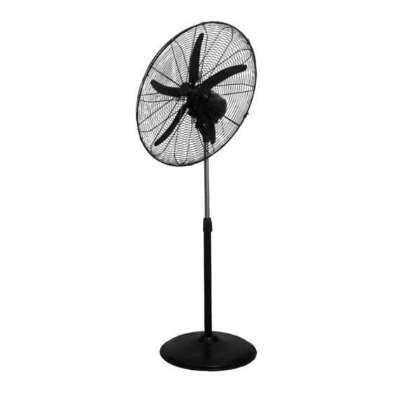
- Page 1 Patio Fan User Manual Model No.: HEG66 230 - 240Va.c. 50Hz 140W Rev 1 Note: The specifications and/or components of this appliance are subject to change without prior notice.
-
Page 2: Table Of Contents
1 Safety Instructions ................. 3 2 Components ................... 6 3 Assembly ..................7 3.1 Base and Stand Post ................... 7 3.2 Attach Motor Head to Stand................ 9 3.3 Safety Grille and Fan Blade ...............10 4 Instructions for Use ..............13 4.1 Head Tilt ......................13 4.2 Fan On / Off / Speed ...................13 4.3 Oscillation....................13... -
Page 3: Safety Instructions
1 Safety Instructions When using electrical appliances, basic safety precautions should always be followed, including the following: • Carefully read this instruction manual before using appliance. Ensure that the fan is switched off from the supply mains before removing • the guard. - Page 4 If the supply cord is damaged, it must be replaced by the manufacturer, its • service agent or similarly qualified persons in order to avoid a hazard. The use of accessories not intended for use with this appliance may cause •...
- Page 5 Additional Safety Instructions If using an extension cord: The technical specifications of the extension cord must match or exceed the • technical specifications of this appliance. Do not allow the cord to hang over the edge of the work surface or to come •...
-
Page 6: Components
2 Components Front Grille Clamp Ring Fan Blade Lower Post Grille Nut and Bolt Cover Rear Grille Base Rear Grille Screws and Washers Washer Motor Head Assembly Locking Lever Locking Thumb Screw Page 6 of 16... -
Page 7: Assembly
3 Assembly 3.1 Base and Stand Post Your Fan has been boxed unassembled to minimise packaging waste. Each part is designed to fit together and be disassembled easily for cleaning or storage. First, unscrew the Locking Lever and Washer from the bottom of the stand post. •... - Page 8 Stand the base upright on the floor. • • Fully unscrew (anticlockwise) the clamp ring at the top of the stand post and remove the clamp ring. Place the Cover over the top of the post and drop down • Page 8 of 16...
-
Page 9: Attach Motor Head To Stand
• Drop the cover all the way down so that it sits on top of the base and covers the base screws. Refit the clamp ring • 3.2 Attach Motor Head to Stand Grasp the end of the chrome tube and pull the chrome tube out as far as it will go, •... -
Page 10: Safety Grille And Fan Blade
Align the head assembly motor mount over the top of the chrome tube in the stand • and then lower down. Tighten the locking thumb screw on the back of the motor mount until secure • 3.3 Safety Grille and Fan Blade To assemble the safety grille and blade assembly, first remove the 4 screws and •... - Page 11 Next, rotate the motor spindle until the “flat” surface is facing up. • Slide the fan blade onto the spindle ensuring the screw is lined up with the “flat” • surface on the spindle as shown. Note: you may need to unscrew (anti-clockwise) the screw a few turns to allow the fan blade to slide onto the motor spindle.
- Page 12 • Take the front grill and open up all the side locking clips. Using a small Philips Head Screw Driver remove the small nut and bolt from the • bottom of the grille and keep in a safe place. • Place the front grille into position by lining up the location fork over the top of the rear grill as shown and push down.
-
Page 13: Instructions For Use
4 Instructions for Use Remove all packaging and unravel the cordset before operation. 4.1 Head Tilt The Fan Head can be adjusted Up and Down so as to blow air at the required angle. Turn off and unplug prior to adjusting. To adjust, grasp the Fan Grills and tilt the head either upward or downward to your desired angle. -
Page 14: Height Adjustment
4.4 Height Adjustment Caution: The fan head assembly is very heavy. Ensure the weight of the head assembly is being held securely whilst the clamp ring is loosened as it may drop. The height of the fan can be adjusted. Unscrew to loosen the clamp ring (Anticlockwise), slide the inner chrome post up or down to your desired height and then re-tighten the clamp ring (Clockwise) to lock in place. -
Page 15: Warranty Against Defect
7 Warranty Against Defect 12 Month Warranty Thank you for your purchase from Kmart. Kmart Australia Ltd warrants your new product to be free from defects in materials and workmanship for the period stated above, from the date of purchase, provided that the product is used in accordance with accompanying recommendations or instructions where provided. - Page 16 Page 16 of 16...
Need help?
Do you have a question about the HEG66 and is the answer not in the manual?
Questions and answers