
Subscribe to Our Youtube Channel
Related Manuals for Insinger TRAC 321-2 SERIES


Summary of Contents for Insinger TRAC 321-2 SERIES
- Page 1 TECHNICAL MANUAL Installation, Operation and Maintenance Instructions TRAYWASHER TRAC 321-2 SERIES TRAC 321-2 TRAC 321-2RPW Insinger Machine Company 6245 State Road Philadelphia, PA 19135-2996 800-344-4802 Fax 215-624-6966 www.insingermachine.com...
- Page 2 Part 2 7-12 information available. Installation Instructions • General Installation Instructions Each piece of equipment at Insinger is carefully tested • Installation Drawings before shipment for proper operation. If the need for service should arise please contact your local Part 3 Authorized Insinger Service Company.
- Page 3 S/S frame, legs and feet ƒ S/S front enclosure panel ƒ Automatic tank fill Insinger’s traywashers were developed specifically ƒ to optimally clean and sanitize ware by reaching all Low water protection ƒ corners and crevices with a vertical spray.
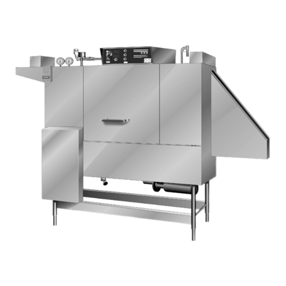
- Page 4 ® PART 1 TECHNICAL INFORMATION TRAC 321-2 Automatic Single Tank Tray Washer SPECIFICATIONS Capacity Per Hour 528 trays CONSTRUCTION- Hood and tank constructed of 16 gauge type Tank Capacity 24.1 gallons 304 S/S. Hood unit of all welded seamless construction. S/S frame, legs and feet.
- Page 5 S/S frame, legs and feet ƒ S/S front enclosure panel ƒ Automatic tank fill Insinger’s traywashers were developed specifically ƒ to optimally clean and sanitize ware by reaching all Low water protection ƒ corners and crevices with a vertical spray.
- Page 6 ® PART 1 TECHNICAL INFORMATION TRAC 321-2 RPW Automatic Double Tank Tray Washer SPECIFICATIONS Capacity Per Hour 528 trays CONSTRUCTION- Hood and tank constructed of 16 gauge type Tank Capacity 10.3 gallons (pre-wash) 304 S/S. Hood unit of all welded seamless construction. S/S 22.5 gallons (wash) frame, legs and feet.
- Page 7 This service is included in the purchase price of your new Insinger dishwasher. We will provide an authorized factory service technician for the initial start-up of your new Insinger dishwasher to ensure it is SAFETY SUMMARY running correctly. Please call the factory or your local...
- Page 8 15 months from the date nor liable for any conditions of erosion or corrosion of shipment from Insinger or 1 year (12 months) caused by corrosive detergents, acids, lye or other from the date of installation or start-up that said...
-
Page 9: Installation Instructions
® PART 2 INSTALLATION INSTRUCTIONS TRAC 321-2 TRAYWASHER SERIES CAUTION: INSTALLATION INSTRUCTIONS As with any 3 phase system, an electrician must These installation instructions are intended for qualified check all motors for proper phasing, i.e., Pump equipment installers: motors must be running in direction indicated by arrow on housing. - Page 10 ® PART 2 INSTALLATION INSTRUCTIONS HVAC Ventilation system should be sized to provide adequate ventilation per machine specs. Refer to spec sheet. Stainless steel, watertight ducting should be connected to the vent cowls on each end of the machine. Refer to spec sheet and installation drawing.
- Page 11 ® PART 2 INSTALLATION INSTRUCTIONS Installation Drawing : TRAC 321-2 RH TRAC321-2 Series Technical Manual 2018 www.insingermachine.com 800-344-4802...
- Page 12 ® PART 2 INSTALLATION INSTRUCTIONS Installation Drawing : TRAC 321-2 LH TRAC321-2 Series Technical Manual 2018 www.insingermachine.com 800-344-4802...
- Page 13 ® PART 2 INSTALLATION INSTRUCTIONS Installation Drawing : TRAC 321-2 RPW RH TRAC321-2 Series Technical Manual 2018 www.insingermachine.com 800-344-4802...
- Page 14 ® PART 2 INSTALLATION INSTRUCTIONS Installation Drawing : TRAC 321-2 RPW LH TRAC321-2 Series Technical Manual 2018 www.insingermachine.com 800-344-4802...
- Page 15 ® PART 3 OPERATION INSTRUCTIONS WASHING A TRAY TRAC 321-2 TRAYWASHER SERIES 1. Place the tray on the conveyor belt. The tray will OPERATION INSTRUCTIONS pass through the machine cycles. These instructions are intended for the daily users of this machine: NOTE: PREPARING MACHINE...
- Page 16 ® PART 4 CLEANING INSTRUCTIONS TRAC 321-2 TRAYWASHER SERIES CLEANING INSTRUCTIONS DAILY CLEANING The following cleaning procedures should be done daily, at the end of the shift: 1. Remove all internal removable parts including spray manifolds, scrap screens, drain overflow tubes, suction strainers and curtains.
- Page 17 ® PART 5 MAINTENANCE & REPAIR PROCEDURES TRAC 321-2 TRAYWASHER SERIES MAINTENANCE REQUIREMENTS This section is intended for qualified service and/or maintenance technicians. The following maintenance should be conducted quarterly: 1. Remove and clean the strainer screens on water and steam lines. If the screens cannot be cleaned, replace.
- Page 18 ® PART 5 MAINTENANCE & REPAIR PROCEDURES Tank Heat Temperature Adjustment Troubleshooting Tank Temperatures A temperature control board is provided in the control If the temperature does not change follow the below panel for easy adjustment of tank temperature. procedures. Though tank temperature is set during factory testing Electric Heat: it is sometimes necessary to re-adjust the temperature...
- Page 19 MAINTENANCE & REPAIR PROCEDURES Motor Overloads Level System All motors used on Insinger Machines are provided The level control system consists of one level timer with motor overloads. Motor overloads are adjusted (P/N DE7-35) and one level float (P/N DE5-60) in the when the machines are factory tested.
- Page 20 ® PART 5 MAINTENANCE & REPAIR PROCEDURES SK-5825 : Final Rinse Solenoid Valve TRAC321-2 Series Technical Manual 2018 www.insingermachine.com 800-344-4802...
- Page 21 ® PART 5 MAINTENANCE & REPAIR PROCEDURES SK-4703 : Electric Heater Installation TRAC321-2 Series Technical Manual 2018 www.insingermachine.com 800-344-4802...
- Page 22 ® PART 5 MAINTENANCE & REPAIR PROCEDURES SK-2397 : 1/2 HP Pump REV C - 03/06/18 ITEM PART NO. DESCRIPTION Motor 1/2 HP D431 Adapter D432 Impeller 3” D434 Casing D2-532 O-Ring D2-533 Flinger D2-534 Seal Assembly D329-5 Drain Petcock 1/4” IPS D3-808 Impeller Retaining Nut 3 Phase Motors Only...
- Page 23 ® PART 5 MAINTENANCE & REPAIR PROCEDURES SK-2923 : 2 HP Pump REV B - 04/10/06 ITEM PART NO. DESCRIPTION Motor 2 HP D431 Adapter D443 Impeller 4 3/8” D434 Casing D2-532 O-Ring D2-533 Flinger D2-534 Seal Assembly D329-5 Drain Petcock 1/4” IPS D3-808 Impeller Retaining Nut TRAC321-2 Series Technical Manual 2018...
- Page 24 ® PART 5 MAINTENANCE & REPAIR PROCEDURES SK-4835 : 3 HP Scot 17 Pump REV A - 06/06/06 ITEM PART NO. DESCRIPTION Motor 3 HP 104.000.165 Flinger 116.000.117 O-Ring, Shaft 110.000.178 Shaft Sleeve, Bronze 132.000.194 Adapter, Iron - JM140/180 101.000.168 Seal, 1 1/2”...
- Page 25 ® PART 5 MAINTENANCE & REPAIR PROCEDURES TROUBLESHOOTING TECHNICAL ISSUES POSSIBLE CAUSES SOLUTIONS Machine will not operate 1. No power 1. Check power supply 2. Blown fuse or tripped breaker 2. Replace fuse; reset breaker 3. Motor overloads tripped 3. Reset overload Tank will not hold water 1.
- Page 26 ® PART 5 MAINTENANCE & REPAIR PROCEDURES TROUBLESHOOTING TECHNICAL ISSUES POSSIBLE CAUSES SOLUTIONS Tank not filling/tank heat 1. Level float dirty 1. Clean level float coming on with no water in 2. Level control system not working 2. Troubleshoot level control circuit tank Tank temperature too low/high 1.
- Page 27 ® PART 6 PARTS AND ASSEMBLIES SK-3246 : TRAC 321-2 Assembly REV E - 05/04/16 TRAC321-2 Series Technical Manual 2018 www.insingermachine.com 800-344-4802...
- Page 28 ® PART 6 PARTS AND ASSEMBLIES SK-3246 : TRAC 321-2 Assembly ITEM PART NO. DESCRIPTION 1094-121 Drive Mechanism D2-554-2A Plug 3/4-10 UNC with Hole D2-554-2 Plug 3/4-10 UNC Pump/Motor - Wash (2 or 3 HP) 1094-30 Final Rinse Assembly 1072-27 Tank Fill Assembly - Auto 973-27 Tank Fill Assembly - Manual...
- Page 29 ® PART 6 PARTS AND ASSEMBLIES SK-3246 : TRAC 321-2 Assembly ITEM PART NO. DESCRIPTION 1361-241 Urethane Crown & Retainer Assembly for Cradle 1098-73 Mechanism Guard 954-50 Drain Assembly 973-21 Curtain Plate 1094-14 Spray Manifold - Wash 1094-97 Chain Assembly (Stand Alone Washer) 1094-33 Curtain - Enter 1094-40...
- Page 30 ® PART 6 PARTS AND ASSEMBLIES SK-3242 : TRAC 321-2 RPW Assembly REV F - 05/04/16 TRAC321-2 Series Technical Manual 2018 www.insingermachine.com 800-344-4802...
- Page 31 ® PART 6 PARTS AND ASSEMBLIES SK-3242 : TRAC 321-2 RPW Assembly ITEM PART NO. DESCRIPTION 1094-121 Drive Mechanism D2-554-2A Plug 3/4-10 UNC with Hole D2-554-2 Plug 3/4-10 UNC Pump/Motor - Prewash (1/2 HP) Pump/Motor - Wash (2 or 3 HP) 1094-30 Final Rinse Assembly 1072-27...
- Page 32 ® PART 6 PARTS AND ASSEMBLIES SK-3242 : TRAC 321-2 RPW Assembly ITEM PART NO. DESCRIPTION 1098-73 Mechanism Guard 954-50 Drain Assembly 973-21 Curtain Plate 1094-14 Spray Manifold - Wash 1098-146 Chain Assembly (Stand Alone Washer) 1094-33 Curtain - Enter 1094-40 Curtain - Center 1094-38...
- Page 33 ® PART 6 PARTS AND ASSEMBLIES 982-54 : Drive Assembly REV F - 02/10/09 ITEM PART NO. DESCRIPTION 982-55 Drive Shaft 975-55 Sprocket, Conveyor Chain 982-56 Sprocket (41B14 7/8 Bore) D2-525 Washer 1 3/8” x 7/8” x 1/8” D2-585 O-Ring (01-115) D311-1 Cotter Pin 1/8”...
- Page 34 ® PART 6 PARTS AND ASSEMBLIES 982-58 : Follower Shaft Assembly REV E - 08/29/02 ITEM PART NO. SIZE DESCRIPTION 975-43A Follower Shaft Channel RH & LH 1 EA 982-59 Shaft D2857 Sprocket, UHMW D2859 Hub Spacer x 7/8” Lg. D2-525 Spacer Cotter Pin 1/8”...
- Page 35 ® PART 6 PARTS AND ASSEMBLIES 1094-121 : Drive Mechanism Assembly REV D - 04/26/02 TRAC321-2 Series Technical Manual 2018 www.insingermachine.com 800-344-4802...
- Page 36 ® PART 6 PARTS AND ASSEMBLIES 1094-121 : Drive Mechanism Assembly ITEM PART NO. DESCRIPTION SEE CHART Gearmotor Brother BGLM18 SEE CHART Sprocket, Drive D2647 Sprocket, Drive 14T with Keyway 820-35 Sprocket, Assembly, Idler 1397-4 Adjustable Spring Stop 1397-6 Pivot Shaft Weldment 1397-2 Idler Sprocket Arm D2780...
- Page 37 ® PART 6 PARTS AND ASSEMBLIES 1361-148 : Drive & Chain Assembly w/ Tray Dryer (Brother AC) REV C - 01/29/10 TRAC321-2 Series Technical Manual 2018 www.insingermachine.com 800-344-4802...
- Page 38 ® PART 6 PARTS AND ASSEMBLIES 1361-148 : Drive & Chain Assembly w/ Tray Dryer (Brother AC) ITEM PART NO. DESCRIPTION SEE CHART Gearmotor, Brother BGLM18 1361-137 Pivot Shaft Mounting Plate SEE CHART Motor Sprocket 820-35 Sprocket Assembly, Idler 1361-149 Drive Shaft Assembly D308B-41 #41 Chain (See Chart)
- Page 39 ® PART 6 PARTS AND ASSEMBLIES 1361-214 : Drive & Chain Assembly (Dayton DC) REV A - 01/29/10 TRAC321-2 Series Technical Manual 2018 www.insingermachine.com 800-344-4802...
- Page 40 ® PART 6 PARTS AND ASSEMBLIES 1361-214 : Drive & Chain Assembly (Dayton DC) ITEM PART NO. DESCRIPTION Motor, Dayton 4Z130A 1361-137 Pivot Shaft Mounting Plate 1165-29 Sprocket, 41B18 820-35 Sprocket Assembly, Idler 1361-149 Drive Shaft Assembly D308C-41-CL Chain, #41 x 53 Links 1361-31 Cover, Gear Motor 1361-157...
- Page 41 ® PART 6 PARTS AND ASSEMBLIES SK-5116 : Chain Assembly Chart REV A - 05/10/16 TRAC321-2 Series Technical Manual 2018 www.insingermachine.com 800-344-4802...
- Page 42 ® PART 6 PARTS AND ASSEMBLIES 973-16 : Chain Guide REV B - 06/24/96 TRAC321-2 Series Technical Manual 2018 www.insingermachine.com 800-344-4802...
- Page 43 ® PART 6 PARTS AND ASSEMBLIES 973-16A : Chain Guide (Poly Strip) REV B - 06/24/96 TRAC321-2 Series Technical Manual 2018 www.insingermachine.com 800-344-4802...
- Page 44 ® PART 6 PARTS AND ASSEMBLIES 982-39 : Chain Guide & Track Bracket Assembly REV A - 12/28/82 TRAC321-2 Series Technical Manual 2018 www.insingermachine.com 800-344-4802...
- Page 45 ® PART 6 PARTS AND ASSEMBLIES 1098-75 : Photoelectric Eye Installation REV B - 07/05/00 TRAC321-2 Series Technical Manual 2018 www.insingermachine.com 800-344-4802...
- Page 46 ® PART 6 PARTS AND ASSEMBLIES 954-1 : Drain Assembly ITEM PART NO. SIZE DESCRIPTION TRAC 321 TRAC 321 954-50A Upper Valve Body 954-50B Lower Valve Body Required per 954-50C O-Ring Nut machine 954-50D Overflow Tube “A” D-193 Skimmer Cup 7 5/16”...
- Page 47 ® PART 6 PARTS AND ASSEMBLIES 1072-55 : Single Drain Assembly LH REV C - 01/13/10 ITEM PART NO. DESCRIPTION 954-1 Drain Assembly D207A-B16-146 Copper Tubing 2” CTS x 36 1/2” Lg. D207A-B12-16 Copper Tubing 1 1/2” CTS x 4” Lg. D207A-B12-12 Copper Tubing 1 1/2”...
- Page 48 ® PART 6 PARTS AND ASSEMBLIES 1072-56 : Single Drain Assembly RH REV B - 01/13/10 ITEM PART NO. DESCRIPTION 954-1 Drain Assembly D207A-B16-94 Copper Tubing 2” CTS x 23 1/2” Lg. D207A-B12-18 Copper Tubing 1 1/2” CTS x 4 1/2” Lg. D207A-B12-8 Copper Tubing 1 1/2”...
- Page 49 ® PART 6 PARTS AND ASSEMBLIES 973-27 : TRAC 321-2 Manual Tank Fill Assembly REV F - 08/27/01 ITEM PART NO. DESCRIPTION D2241 Vacuum Breaker 1/2” IPS D2339 Ball Valve 1/2” IPS D316F-D1-D2 Street Elbow 90 1/2” IPS D315F-D1-D3 Elbow 45 1/2”...
- Page 50 ® PART 6 PARTS AND ASSEMBLIES 973-28 : TRAC 321-2 Auto Tank Fill Assembly REV F - 08/29/01 ITEM PART NO. DESCRIPTION D2241 Vacuum Breaker 1/2” IPS D2930 Solenoid Valve 1/2” IPS D2483A “Y” Strainer D316F-D1-D2 Street Elbow 90 1/2” IPS D315F-D1-D3 Elbow 45 1/2”...
- Page 51 ® PART 6 PARTS AND ASSEMBLIES 1072-26 : TRAC 321-2 RPW Manual Tank Fill Assembly REV D - 08/24/01 ITEM PART NO. DESCRIPTION D2241 Vacuum Breaker 1/2” IPS D2339 Ball Valve 1/2” IPS D316F-D1-D2 Street Elbow 90 1/2” IPS D315F-D1-D3 Elbow 45 1/2”...
- Page 52 ® PART 6 PARTS AND ASSEMBLIES 1072-27 : TRAC 321-2 RPW Auto Tank Fill Assembly REV E - 08/27/01 ITEM PART NO. DESCRIPTION D2241 Vacuum Breaker 1/2” IPS D2930 Solenoid Valve 1/2” IPS D2483A “Y” Strainer D316F-D1-D2 Street Elbow 90 1/2”...
- Page 53 ® PART 6 PARTS AND ASSEMBLIES 1072-16R : Prewash Discharge Line Assembly RH REV F - 05/12/99 ITEM PART NO. SIZE DESCRIPTION 963-11 Discharge Nipple D326J-H1 Locknut 1 1/2” IPS 1072-14R Discharge Manifold 970-25A Spray Pipe Extension 562-87A Locking Screw 982-66 Spray Pipe D-2712...
- Page 54 ® PART 6 PARTS AND ASSEMBLIES 1072-16L : Prewash Discharge Line Assembly LH REV F - 05/12/99 ITEM PART NO. SIZE DESCRIPTION 963-11 Discharge Nipple D326J-H1 Locknut 1 1/2” IPS 1072-14L Discharge Manifold 970-25A Spray Pipe Extension 562-87A Locking Screw 982-66 Spray Pipe D-2712...
- Page 55 ® PART 6 PARTS AND ASSEMBLIES 1094-10 : Discharge Line Assembly REV D - 11/08/99 ITEM PART NO. SIZE DESCRIPTION Discharge Manifold 1094-11 for 2 HP Motor 1176-17 for 3 HP Motor 1493-6R for Gas Heat RH 3 HP Motor 1493-6L for Gas Heat LH 3 HP Motor 1094-17...
- Page 56 ® PART 6 PARTS AND ASSEMBLIES 982-30A : Final Rinse Piping Assembly REV F - 06/12/15 ITEM PART NO. DESCRIPTION STANDARD CHEMICAL D2483A “Y” Strainer 1/2” IPS D314F-DC-00 Close Nipple 1/2” IPS D320F-D1D1D1 Tee 1/2” IPS D322F-D2-B1 Hex Reducer 1/2” MIPS x 1/4” FIPS D2497 Petcock 1/4”...
- Page 57 ® PART 6 PARTS AND ASSEMBLIES 1094-30 : Final Rinse Piping Assembly REV F - 12/15/99 ITEM PART NO. DESCRIPTION 982-30A Final Rinse Piping Assembly 1094-29 Manifold Assembly - Final Rinse 982-28 Spray Pipe S/S 1/2” IPS for Standard 982-28B for 2”...
- Page 58 ® PART 6 PARTS AND ASSEMBLIES 1094-4 : TRAC 321-2 Scrap Screen Locations REV B - 12/30/11 TRAC321-2 Series Technical Manual 2018 www.insingermachine.com 800-344-4802...
- Page 59 ® PART 6 PARTS AND ASSEMBLIES 1098-7R : TRAC 321-2 RPW Scrap Screen Locations RH REV B - 12/30/11 TRAC321-2 Series Technical Manual 2018 www.insingermachine.com 800-344-4802...
- Page 60 ® PART 6 PARTS AND ASSEMBLIES 1098-7L : TRAC 321-2 RPW Scrap Screen Locations LH REV B - 12/30/11 TRAC321-2 Series Technical Manual 2018 www.insingermachine.com 800-344-4802...
- Page 61 ® PART 6 PARTS AND ASSEMBLIES 1443-1 : TRAC 321-2 S/S Guide Rails REV G - 01/28/10 TRAC321-2 Series Technical Manual 2018 www.insingermachine.com 800-344-4802...
- Page 62 ® PART 6 PARTS AND ASSEMBLIES 1443-1 : TRAC 321-2 S/S Guide Rails REV G - 01/28/10 TRAC321-2 Series Technical Manual 2018 www.insingermachine.com 800-344-4802...
- Page 63 ® PART 6 PARTS AND ASSEMBLIES 1444-1 : TRAC 321-2 RPW S/S Guide Rails REV G - 01/28/10 TRAC321-2 Series Technical Manual 2018 www.insingermachine.com 800-344-4802...
- Page 64 ® PART 6 PARTS AND ASSEMBLIES 1444-1 : TRAC 321-2 RPW S/S Guide Rails REV G - 01/28/10 TRAC321-2 Series Technical Manual 2018 www.insingermachine.com 800-344-4802...
- Page 65 ® PART 6 PARTS AND ASSEMBLIES 1448-19 : TRAC 321-2 Pobco Guide Rails REV A - 10/02/95 TRAC321-2 Series Technical Manual 2018 www.insingermachine.com 800-344-4802...
- Page 66 ® PART 6 PARTS AND ASSEMBLIES 1448-19 : TRAC 321-2 Pobco Guide Rails REV A - 10/02/95 TRAC321-2 Series Technical Manual 2018 www.insingermachine.com 800-344-4802...
- Page 67 ® PART 6 PARTS AND ASSEMBLIES 1449-13 : TRAC 321-2 RPW Pobco Guide Rails REV A - 03/24/15 TRAC321-2 Series Technical Manual 2018 www.insingermachine.com 800-344-4802...
- Page 68 ® PART 6 PARTS AND ASSEMBLIES 1449-13 : TRAC 321-2 RPW Pobco Guide Rails REV A - 03/24/15 TRAC321-2 Series Technical Manual 2018 www.insingermachine.com 800-344-4802...
- Page 69 ® PART 6 PARTS AND ASSEMBLIES SK-2485 : Tray Rest S/S Guide Rail REV E - 12/17/04 TRAC321-2 Series Technical Manual 2018 www.insingermachine.com 800-344-4802...
- Page 70 ® PART 6 PARTS AND ASSEMBLIES SK-2485 : Tray Rest Pobco Guide Rail REV F - 05/05/15 TRAC321-2 Series Technical Manual 2018 www.insingermachine.com 800-344-4802...
- Page 71 ® PART 6 PARTS AND ASSEMBLIES 982-48R : Electric Booster Assembly RH REV E - 06/01/10 TRAC321-2 Series Technical Manual 2018 www.insingermachine.com 800-344-4802...
- Page 72 ® PART 6 PARTS AND ASSEMBLIES 982-48R : Electric Booster Assembly RH ITEM PART NO. DESCRIPTION C24-58 Electric Booster Relief Valve 3/4” IPS D316A-D3 Elbow 1/2” C 925-49 Bracket D2508 Pressure Regulator D2340 Ball Valve 3/4” IPS D320F-E1-E1-E1 Tee 3/4” IPS D322F-E2-B1 Reducer 3/4”...
- Page 73 ® PART 6 PARTS AND ASSEMBLIES 982-19 : Steam Injector REV A - 08/31/82 ITEM PART NO. DESCRIPTION D-2483 “Y” Strainer 1/2” IPS D-942 Penberthy Injector 1/2” IPS D2945 Solenoid - Asco 1/2” IPS D-2453 Check Valve 1/2” IPS D316A-D1-D2 Street Elbow 1/2”...
- Page 74 ® PART 6 PARTS AND ASSEMBLIES 1098-55R : Steam Coil Assembly RH REV E - 02/19/10 ITEM PART NO. SIZE DESCRIPTION 982-46 Steam Coil S/S D326A-D Locknut 1/2” IPS D314A-D2-30 Nipple 1/2” IPS x 3 3/4” Lg. D316A-D1 Elbow 1/2” IPS D314A-D2-20 Nipple 1/2”...
- Page 75 ® PART 6 PARTS AND ASSEMBLIES 1098-55L : Steam Coil Assembly LH REV E - 02/19/10 ITEM PART NO. SIZE DESCRIPTION 982-46 Steam Coil S/S D326A-D Locknut 1/2” IPS D314A-D2-30 Nipple 1/2” IPS x 3 3/4” Lg. D316A-D1 Elbow 1/2” IPS D314A-D2-20 Nipple 1/2”...
- Page 76 ® PART 6 PARTS AND ASSEMBLIES 1394-7 : Steam Booster Assembly REV F - 11/08/05 TRAC321-2 Series Technical Manual 2018 www.insingermachine.com 800-344-4802...
- Page 77 ® PART 6 PARTS AND ASSEMBLIES 1394-7 : Steam Booster Assembly ITEM PART NO. DESCRIPTION D-2100 Steam Booster (I-2) 278-1 Booster Stand D314F-FC-00 Close Nipple 1” IPS D316A-F3-F2 Street Elbow 1” C x 1” MIPS D316A-D3-D2 Elbow 1/2” C x 1/2” MIPS D207A-K8-23 Copper Tubing 1”...
- Page 78 ® PART 6 PARTS AND ASSEMBLIES 982-45 : Piping Assembly Steam Booster to Final Rinse REV A - 09/20/17 ITEM PART NO. DESCRIPTION 1447-1 Steam Booster Weldment 1394-7 Steam Booster Piping Assembly 70 Rise D316A-D3 Elbow 1/2” C D207A-B4-172 Copper Tubing 1/2” x 43” Lg. D319A-D3-D2 Union Elbow 1/2”...
- Page 79 ® PART 7 ELECTRICAL SCHEMATICS & PARTS WTRAC010 : Steam Heat AC Drive Motor TRAC321-2 Series Technical Manual 2018 www.insingermachine.com 800-344-4802...
- Page 80 ® PART 7 ELECTRICAL SCHEMATICS & PARTS WTRAC011 : Steam Heat AC Drive Motor (Security) TRAC321-2 Series Technical Manual 2018 www.insingermachine.com 800-344-4802...
- Page 81 ® PART 7 ELECTRICAL SCHEMATICS & PARTS WTRACNEW : Steam Heat DC Drive Motor (Security) TRAC321-2 Series Technical Manual 2018 www.insingermachine.com 800-344-4802...
- Page 82 ® PART 7 ELECTRICAL SCHEMATICS & PARTS WTRAC020 : Electric Heat AC Drive Motor TRAC321-2 Series Technical Manual 2018 www.insingermachine.com 800-344-4802...
- Page 83 ® PART 7 ELECTRICAL SCHEMATICS & PARTS WTRAC021 : Electric Heat AC Drive Motor (Security) TRAC321-2 Series Technical Manual 2018 www.insingermachine.com 800-344-4802...
- Page 84 ® PART 7 ELECTRICAL SCHEMATICS & PARTS WTRAC071 : Gas Heat (Security) TRAC321-2 Series Technical Manual 2018 www.insingermachine.com 800-344-4802...
- Page 85 ® PART 7 ELECTRICAL SCHEMATICS & PARTS WTRAC071 : Gas Heat (Security) TRAC321-2 Series Technical Manual 2018 www.insingermachine.com 800-344-4802...
- Page 86 ® PART 7 ELECTRICAL SCHEMATICS & PARTS SK-3126 : Control Panel Layout (AC Drive) REV U - 03/08/18 TRAC321-2 Series Technical Manual 2018 www.insingermachine.com 800-344-4802...
- Page 87 ® PART 7 ELECTRICAL SCHEMATICS & PARTS SK-3126 : Control Panel Layout (AC Drive) ITEM PART NO. DESCRIPTION SK-3773 Component Mounting Plate DE6-9 Control Transformer (150 VA, 24 VAC) DE9-164 Fuse Block (150 & 250 VA XFMR) Fuse (150 VA Transformer Primary) DE9-167 460V, FNQ-R-1...
- Page 88 ® PART 7 ELECTRICAL SCHEMATICS & PARTS SK-3126 : Control Panel Layout (AC Drive) ITEM PART NO. DESCRIPTION DE3-39 Terminal Section DE3-40 Terminal End Cover Plate DE3-41 Terminal End Clamp DE9-251 Temperature Control Board Drive Transformer (250 VA, 120 VAC) DE6-10 All except 208 &...
- Page 89 ® PART 7 ELECTRICAL SCHEMATICS & PARTS SK-3126 : Control Panel Layout (AC Drive) ITEM PART NO. DESCRIPTION DE3-152 Power Distribution Block DE9-186 Fuse Block (Single Point Connection) DE2-60 Overload Base DE8-59 Contact Block, NO Fuse Single Point Connection PARTS NOT SHOWN Electric Immersion Heater (5kW) DE13-SD73 440 - 480 V,...
- Page 90 ® PART 7 ELECTRICAL SCHEMATICS & PARTS SK-3805 : Control Panel Layout Security Pkg (AC Drive) REV N - 03/08/18 FUSE REQUIREMENTS FUSE PART NO. 208 V 230 V 380 V 460 V FNQ-R-6 DE9-177 TRAC 321 10 A FNQ-R-10 DE9-181 2 HP Wash Pump 15 A...
- Page 91 ® PART 7 ELECTRICAL SCHEMATICS & PARTS SK-3805 : Control Panel Layout Security Pkg (AC Drive) ITEM PART NO. DESCRIPTION SK-3806 Component Mounting Plate DE6-9 Control Transformer (150 VA, 24 VAC) DE9-185 Fuse Block, 2 Pole Fuse (150 VA Transformer Primary) DE9-167 460V, FNQ-R-1...
- Page 92 ® PART 7 ELECTRICAL SCHEMATICS & PARTS SK-3805 : Control Panel Layout Security Pkg (AC Drive) ITEM PART NO. DESCRIPTION DE3-43 Relay Hold Down Spring DE9-84 DIN Rail (35 mm) DE3-42 DIN Rail (15 mm) DE3-39 Terminal Section DE3-40 Terminal End Cover Plate DE3-41 Terminal End Clamp DE9-251...
- Page 93 ® Insinger Machine Company 6245 State Road Philadelphia, PA 19135-2996 800-344-4802 Fax 215-624-6966 www.insingermachine.com...
Need help?
Do you have a question about the TRAC 321-2 SERIES and is the answer not in the manual?
Questions and answers