Advertisement
Operator's Manual
For Cub Cadet Series 3000 Tractors
NOTE:
Front Hitch System Model No. 190-343-100
Must be Installed on Tractor.
INSTALLATION
MAINTENANCE INSTRUCTIONS
READ SAFETY RULES AND INSTRUCTIONS CAREFULLY
CUB CADET P.O. BOX 368023 CLEVELAND, OHIO 44136-9722 [www.cubcadet.com]
PRINTED IN U.S.A.
ECO 02090
SNOW THROWER
ATTACHMENT
Model Number
IMPORTANT:
AND
353
FORM NO. 770-0847C
(7/00)
Advertisement

Summary of Contents for Cub Cadet 353
- Page 1 Front Hitch System Model No. 190-343-100 Must be Installed on Tractor. INSTALLATION MAINTENANCE INSTRUCTIONS Model Number IMPORTANT: READ SAFETY RULES AND INSTRUCTIONS CAREFULLY CUB CADET P.O. BOX 368023 CLEVELAND, OHIO 44136-9722 [www.cubcadet.com] PRINTED IN U.S.A. FORM NO. 770-0847C (7/00) ECO 02090...
-
Page 2: Table Of Contents
CONTENTS Section Page Safe Operation ....................... To The Owner ......................Introduction ......................Assembly, Installation and Removal ............... Adjustments and Operation ..................Maintenance ......................Warranty ......................... IMPORTANT SAFE OPERATION PRACTICES THIS SYMBOL POINTS OUT IMPORTANT SAFETY INSTRUCTIONS WHICH, IF NOT FOLLOWED, COULD ENDANGER THE PERSONAL SAFETY AND/OR PROPERTY OF YOURSELF AND OTHERS. - Page 3 the fuel tank indoors while the engine is running or have stopped completely. Disconnect the spark while the engine is still hot. Replace the gasoline plug wire and keep it away from plug to prevent cap securely and wipe off any spilled gasoline accidental starting.
- Page 4 PRODUCT SAFETY GRAPHICS 3. Replacement safety graphics are available through your Cub Cadet dealer. 1. Keep safety product graphics (decals) clean. 2. Replace any safety graphic that is damaged, destroyed, missing, painted over or can no longer be read. DANGER NEVER PUT HAND IN CHUTE.
-
Page 5: To The Owner
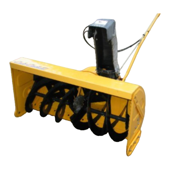
TO THE OWNER The Cub Cadet 45-inch Snow Thrower Attachment, Model Number 353, is designed for use on Cub Cadet Series 3000 Tractors. Contained in this manual are instructions for the installation and use of the snow thrower assembly with these tractors. -
Page 6: Introduction
SECTION I. INTRODUCTION This section will help you to become familiar with the components of the 45 ″ Snow Thrower Attachment, Model 353. Select a firm level surface that is large enough to accommodate both the snow thrower assembly and the tractor w/ front hitch asssembly. - Page 7 CONTENTS OF HARDWARE PACK REF. PART NUMBER DESCRIPTION QTY. 710-3022 Hex Cap Screw, 3/8-16 X 2.75 Lg GR5 712-0431 Hex Flange Lock Nut, 3/8-16 750-0748 Spacer, 3/8 ID x 1.0 OD x 1.25 Lg 714-0507 Cotter Pin, 3/32 X 3/4 Lg 725-0157 Cable Tie 711-1351...
-
Page 8: Assembly, Installation And Removal
SECTION II. ASSEMBLY, INSTALLATION AND REMOVAL. This section contains insructions for final assembly of 2. Position the chute crank support tube (D) to insert the 45 ″ Snow Thrower, and the quick attachment steps the screws (1) into the holes of the support tube for installation and removal of the snow thrower. - Page 9 5. Remove the two socket hd. screws from the split d. Install the front hitch strut (or manual angler- locking collar assembly (6) and install the collar set in center position) with the clevis pins and onto the bottom of the piston of the front hitch lift internal cotter pins.
- Page 10 5. Start the tractor and align the front hitch yoke with 10. Slide the male half shaft into the female half the attachment brackets on each side of the rear 11. Compress the auto-lok collar on the snow thrower blower housing (Refer to Figure 9). drive shaft;...
-
Page 11: Adjustments And Operation
SECTION III. ADJUSTMENTS AND OPERATION A. ADJUSTMENTS 2. Drift Cutters Drift cutters on both sides of the auger housing can be adjusted to the up position for a higher cut. Refer to Figure 12 and proceed as follows: WARNING a. Remove each drift cutter by removing the two If the snow thrower is to be used on gravel surfaces, carriage bolts and hex insert lock nuts. - Page 12 3. Discharge Chute Control Crank 2. Before placing the snow thrower into operation: The discharge chute control crank is located on the a. Check all nuts and bolts for proper tightness. left hand side of the snow thrower. The chute crank Be sure that all parts are properly assembled.
- Page 13 D. SPECIAL PRECAUTIONS E. OPERATING TIPS • Whenever possible, discharge snow down wind. WARNING • DO NOT attempt to clear ice or hard packed- frozen snow. If the snow thrower becomes plugged with snow or • Always overlap each pass slightly to assure jammed due to hitting a foreign object, immediately complete snow removal.
-
Page 14: Maintenance
SECTION IV. MAINTENANCE Section IV describes maintenance procedures de- c. Slide the shave plate out of the off-set slot of signed to keep your snow thrower in good operating the housing, and from between the skid shoes condition. and side panels of the housing. d. - Page 15 LUBRICATION 6. Lubricate the telescoping square spindle of the drive shaft (rear half) using 251H EP grease or an 1. The auger gear box is lubricated with grease at the equivalent No. 2 multi-purpose lithium grease factory and is neither externally servicable, nor once a year.
-
Page 16: Warranty
How to obtain service Contact your authorized Cub Cadet servicing dealer who sold you your Cub Cadet equipment. If this dealer is not available, see the Consumer Yellow Pages under “lawn mowers” for the name of a dealer near you.


Need help?
Do you have a question about the 353 and is the answer not in the manual?
Questions and answers