Advertisement
Safe Operation Practices • Set-Up • Operation • Maintenance • Service • Troubleshooting • Warranty
O
'
M
peratOr
s
anual
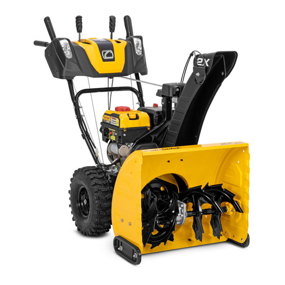
Two Stage Snow Thrower — 2X 24" HP, 2X 26" HP, 2X 524 WE,
2X 524 SWE, 2X 526 SWE, & 2X 528 SWE
WARNING
READ AND FOLLOW ALL SAFETY RULES AND INSTRUCTIONS IN THIS MANUAL
BEFORE ATTEMPTING TO OPERATE THIS MACHINE.
FAILURE TO COMPLY WITH THESE INSTRUCTIONS MAY RESULT IN PERSONAL INJURY.
CUB CADET LLC, P.O. BOX 361131 CLEVELAND, OHIO 44136-0019
Printed In USA
Form No. 769-10699
(April 1, 2015)
Advertisement
Table of Contents

Related Manuals for Cub Cadet 2X 24 HP


Summary of Contents for Cub Cadet 2X 24 HP
- Page 1 READ AND FOLLOW ALL SAFETY RULES AND INSTRUCTIONS IN THIS MANUAL BEFORE ATTEMPTING TO OPERATE THIS MACHINE. FAILURE TO COMPLY WITH THESE INSTRUCTIONS MAY RESULT IN PERSONAL INJURY. CUB CADET LLC, P.O. BOX 361131 CLEVELAND, OHIO 44136-0019 Printed In USA Form No. 769-10699...
-
Page 2: Table Of Contents
See How-to Maintenance and Parts Installation Videos at www.cubcadet.com/tutorials ◊ Call a Customer Support Representative at (800) 965-4CUB ◊ Locate your nearest Cub Cadet Dealer at (877) 282-8684 ◊ Write to Cub Cadet LLC • P.O. Box 361131 • Cleveland, OH • 44136-0019... -
Page 3: Safe Operation Practices
Important Safe Operation Practices WARNING! This symbol points out important safety instructions which, if not followed, could endanger the personal safety and/or property of yourself and others. Read and follow all instructions in this manual before attempting to operate this machine. Failure to comply with these instructions may result in personal injury. - Page 4 Safe Handling of Gasoline Never run an engine indoors or in a poorly ventilated area. Engine exhaust contains carbon monoxide, an odorless To avoid personal injury or property damage use extreme care and deadly gas. in handling gasoline. Gasoline is extremely flammable and the Do not operate machine while under the influence of vapors are explosive.
- Page 5 Clearing a Clogged Discharge Chute According to the Consumer Products Safety Commission (CPSC) and the U.S. Environmental Protection Agency (EPA), Hand contact with the rotating impeller inside the discharge this product has an Average Useful Life of seven (7) years, chute is the most common cause of injury associated with snow or 60 hours of operation.
- Page 6 Safety Symbols This page depicts and describes safety symbols that may appear on this product. Read, understand, and follow all instructions on the machine before attempting to assemble and operate. Symbol Description READ THE OPERATOR’S MANUAL(S) Read, understand, and follow all instructions in the manual(s) before attempting to assemble and operate WARNING—...
-
Page 7: Assembly & Set-Up
Assembly & Set-Up Contents of Carton • Snow Thrower (1) • Replacement Auger Shear Pins (2) • Chute Assembly (1) • Chute Control Rod or Flex Shaft (1) • Engine Manual (1) • Product Registration Card (1) • Snow Thrower Operator’s Manual (1) †... - Page 8 Assembly Secure the handle by tightening the plastic knob located (If Equipped with 4-Way Chute Control on both the left and right sides of the handle. Remove or Chute Tilt Control) and discard any rubber bands, if present. They are for packaging purposes only.
- Page 9 Rotate the joystick to the one o’clock position so that the silver indicator arrow on the pinion gear below the control panel faces upward. See Figure 3-7. Figure 3-5 Squeeze the trigger on the joystick and rotate the chute by hand to face forward.
- Page 10 NOTE: For smoothest operation, the cables should all be to Push the chute control rod toward the control panel until the hole in the rod lines up with the hole in the chute the left of the chute directional control rod. control input closest to the chute control head and insert NOTE: Models with 2-Way Chute Control have only one the hairpin clip removed earlier.
- Page 11 Assembly Secure the handle by tightening the plastic knob located (If Equipped with Overhead Chute Control) on both the left and right sides of the handle. See Figure Handle Assembly 3-14. Remove and discard any rubber bands, if present. They are for packaging purposes only. Place the shift lever in the Forward-6 position.
- Page 12 Place chute assembly onto chute base. Insert the flex shaft into the chute control rod coupling under the dash panel. See Figure 3-18. Secure chute control head to chute support bracket with the lock nuts and hex screws removed earlier. See Figure 3-16.
- Page 13 Adjustments Chute Clean-Out Tool The chute clean-out tool is fastened to the top of the auger Skid Shoes housing with a mounting clip and a cable tie at the factory. Cut the cable tie before operating the snow thrower. See Figure 3-20. The snow thrower skid shoes are adjusted at the factory for shipping purposes.
- Page 14 Auger Control To readjust the control cable, loosen the upper hex screw on the auger cable bracket. WARNING! Prior to operating your snow thrower, Position the bracket upward to provide more slack (or carefully read and follow all instructions below. downward to increase cable tension).
-
Page 15: Controls
Controls and Features Drive Control Shift Lever 4-Way Chute Directional Control/ Chute Tilt Control † Auger Control Headlight Steering Trigger Control † Chute Assembly Clean Out Tool Chute Directional Control † Augers † If Equipped Skid Shoe Figure 4-1 Skid Shoes Snow thrower controls and features are described below and illustrated in Figure 4-1. - Page 16 Auger Control Steering Trigger Controls (If Equipped) The auger control is located on the left handle. Squeeze the The left and right wheel steering trigger controls are located on control grip against the handle to engage the augers and start the underside of the handles.
- Page 17 Chute Directional Control/Chute Tilt Control Chute Clean-Out Tool (If Equipped) WARNING! Never use your hands to clear a clogged chute assembly. Shut off engine and remain CHUTE DIRECTIONAL CONTROL behind handles until all moving parts have stopped before unclogging. The chute clean-out tool is conveniently fastened to the rear of the auger housing with a mounting clip.
-
Page 18: Operation
Operation Starting and Stopping the Engine Replacing Shear Pins Refer to the Engine Operator’s Manual packed with your snow The augers are secured to the spiral shaft with shear pins and thrower for instructions on starting and stopping the engine. cotter pins. -
Page 19: Maintenance & Adjustment
Maintenance & Adjustments Maintenance To remove shave plate: Remove the carriage bolts and hex nuts which attach it to Engine the snow thrower housing. Refer to the Engine Operator’s Manual. Reassemble new shave plate, making sure heads of carriage bolts are to the inside of housing. Tighten securely. Tire Pressure Lubrication Refer to Assembly and Set-up section for information regarding... - Page 20 Gear Shaft NOTE: When lubricating the hex shaft, be careful not to get any oil on the aluminum drive plate or the rubber friction The gear (hex) shaft should be lubricated at least once a season wheel. Doing so will hinder the snow thrower’s drive or after every twenty-five (25) hours of operation.
- Page 21 Drive Control Chute Bracket Adjustment (If Equipped) When the drive control is released and in the disengaged “up” If the spiral at the bottom of the chute directional control is not position, the cable should have very little slack. It should NOT be fully engaging with the chute assembly, the chute bracket can be tight.
- Page 22 Chute Control Rod (4-Way Chute Control) Chute Assembly (Overhead Chute Control) (If Equipped) (If Equipped) To adjust the chute control rod, proceed as follows: If the chute fails to remain stationary during operation, the pre-load of the chute can be adjusted by tightening the hex nut Remove the hairpin clip from the hole closest to the chute found on the front of the chute control assembly.
-
Page 23: Service
Service Belt Replacement Loosen and remove the two bolts and flat washers securing the belt guide. See Figure 7-2. Remove belt guide. Auger Belt To remove and replace your snow thrower’s auger belt, proceed as follows: Allow the engine to run until it is out of fuel. Do not attempt to pour fuel from the engine. - Page 24 Carefully pivot the snow thrower up and forward so that it Remove the belt from around the auger pulley, and slip the rests on the auger housing. belt between the support bracket and the auger pulley. See Figure 7-6. Remove the frame cover from the underside of the snow NOTE: Engaging the auger control will ease removal and thrower by removing the self-tapping screws which secure it.
- Page 25 Follow the instructions below. Examine the friction wheel for signs of wear or cracking and replace if necessary: (2X 24 HP, 2X 524 SWE, 2X 26 HP, 2X 526 SWE, 528 SWE) Allow the engine to run until it is out of fuel. Do not If the snow thrower fails to drive with the drive control engaged, attempt to pour fuel from the engine.
- Page 26 Carefully remove the hex nut which secures the hex shaft Follow the previous steps in reverse order to reassemble to the snow thrower frame and lightly tap the shaft’s end to components. dislodge the ball bearing from the right side of the frame. Perform the Drive Control test on page 21 in the See Figure 7-8.
-
Page 27: Troubleshooting
Troubleshooting Problem Cause Remedy Engine fails to start 1. Choke not in CHOKE position. 1. Move choke to CHOKE position. 2. Spark plug wire disconnected. 2. Connect wire to spark plug. 3. Fuel tank empty or stale fuel. 3. Fill tank with clean, fresh gasoline. 4. -
Page 28: Replacement Parts
Replacement Parts Component Part Number and Description 954-04050A Auger Drive Belt (2X 24” HP, 2X 524 WE, 2X 524 SWE, 2X 26” HP, & 2X 526 SWE) 954-04260 Wheel Drive Belt (2X 24” HP, 2X 524 WE, 2X 524 SWE, 2X 26”... -
Page 29: Attachments
Attachments & Accessories The following attachments and accessories are available for your Cub Cadet snow thrower. See your Cub Cadet dealer or the retailer from which you purchased your snow thrower for information regarding price and availability. Model Number Description... - Page 32 No implied warranty, including any implied warranty of “Cub Cadet” will, at its option, repair or replace, free of charge, any merchantability of fitness for a particular purpose, applies part found to be defective in materials or workmanship. This limited...
Need help?
Do you have a question about the 2X 24 HP and is the answer not in the manual?
Questions and answers
what the motor size of a cub cadet snow blower 2x24
The motor size of the Cub Cadet 2X 24 HP snow blower is 208cc.
This answer is automatically generated
whats the motor size of a 2x2a
The Cub Cadet 2X 24 HP uses a gasoline-powered, four-cycle engine. The exact motor size (in cc or horsepower) is not specified in the provided context.
This answer is automatically generated