Table of Contents
Advertisement
Quick Links
Safety • Set-Up • Operation • Adjustments • Maintenance • Troubleshooting • Parts Lists • Warranty
OPERATOR'S MANUAL
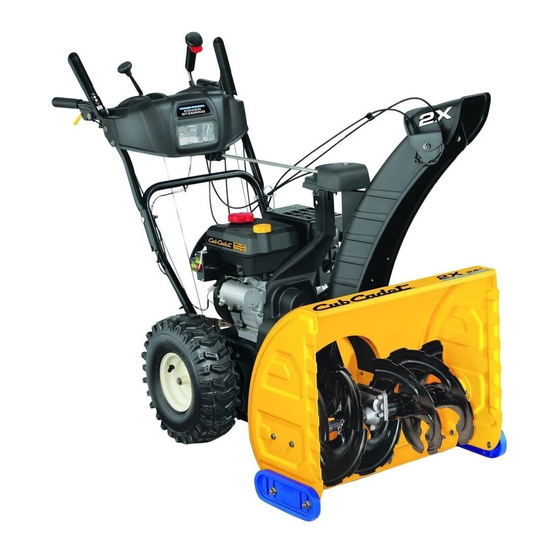
Two-Stage Snow Thrower
IMPORTANT:
READ SAFETY RULES AND
INSTRUCTIONS CAREFULLY
BEFORE OPERATION
60 Ottawa Street South, KITCHENER, ONTARIO N2G 4J1
PRINTED IN U.S.A.
769-04177
06/25/08
Advertisement
Table of Contents

Related Manuals for Cub Cadet 31AH7ZK5596


Summary of Contents for Cub Cadet 31AH7ZK5596
- Page 1 Safety • Set-Up • Operation • Adjustments • Maintenance • Troubleshooting • Parts Lists • Warranty OPERATOR’S MANUAL Two-Stage Snow Thrower IMPORTANT: READ SAFETY RULES AND INSTRUCTIONS CAREFULLY BEFORE OPERATION 60 Ottawa Street South, KITCHENER, ONTARIO N2G 4J1 PRINTED IN U.S.A. 769-04177 06/25/08...
-
Page 2: Table Of Contents
This Operator’s Manual is an important part of your new snow thrower. It will help you assemble, prepare and maintain the unit for best performance. Please read and understand what it says. Table of Contents Safety Symbols ........... 3 Maintaining Your Snow Thrower ...... 14 Safe Operation Practices ........ -
Page 3: Safety Symbols
This page depicts and describes safety symbols that may appear on this product. Read, understand, and follow all instructions on the machine before attempting to assemble and operate. Symbol Description Safety READ THE OPERATOR’S MANUAL(S) Read, understand, and follow all instructions in the manual(s) before Symbols attempting to assemble and operate. -
Page 4: Safe Operation Practices
WARNING: Engine Exhaust, some of its constituents, and certain vehicle compo- nents contain or emit chemicals known to State of California to cause cancer and birth defects or other reproductive harm. DANGER: This machine was built to be operated according to the safe operation practices in this manual. - Page 5 Operation Maintenance & Storage 1. Do not put hands or feet near rotating parts, in the auger/ 1. Never tamper with safety devices. Check their proper impeller housing or chute assembly. Contact with the operation regularly. Refer to the maintenance and adjust- rotating parts can amputate hands and feet.
-
Page 6: Setting Up Your Snow Thrower
Handle Assembly IMPORTANT: The snow thrower is shipped with oil and WITHOUT GASOLINE. After assembly, refer to For shipping purposes, the upper handle is secured separate engine manual for proper fuel and engine oil loosely to the lower handle with wing nuts. recommendations. - Page 7 Setting Up Your Snow Thrower Figure 3-6 Figure 3-5 Drift Cutters (If Equipped) Drift cutters should be used when operating the snow CAUTION thrower in heavy drift conditions. • On models so equipped, drift cutters and hardware IMPORTANT: are assembled to the auger housing inverted. Prior to operating •...
-
Page 8: Operating Your Snow Thrower
Know Your Snow Thrower Track Drive Control Shift Lever Operating Two-Way Chute Control™ (optional) Auger Control Your Snow Headlight Thrower Steering Control Chute Direction Control (optional) Chute Assembly Clean-Out Tool Engine Controls WARNING Choke Control Gas Cap Primer Read, understand, Oil Fill and follow all instruc- tions and warnings... - Page 9 Safety Key Two-Way Chute Control™ (optional) This two-way control lever is meant to control the The safety key must be pushed in place in order for distance of snow discharge from the chute. Tilt the lever the engine to start. Pull the safety key out to prevent forward or rearward to adjust the distance snow will be unauthorized use of equipment.
- Page 10 Track Lock Lever Track Lock The track lock lever is located on the right side of the Lever snow thrower and is used to select the position of the auger housing and the method of track operation. Move the lever to the right, then forward or backward to one of the three positions.
- Page 11 Stopping The Engine Run engine for a few minutes before stopping to help dry off any moisture on the engine. • Push the rocker switch to the “OFF” position. • Pull out the safety key. • Close fuel shut-off valve (If equipped). •...
-
Page 12: Makingadjustments
Shift Cable If the full range of speeds (forward and reverse) cannot be achieved, refer to the figure to the left and adjust the shift cable as follows: 1. Place the shift lever in the fastest forward speed position. Making 2. - Page 13 • Move the shift lever back to the fast reverse position then all the way forward again. There should be no resistance in the shift lever, and the tracks should keep turning. • If you have resistance when moving the shift lever or the tracks stop when they should not, loosen the jam nut on the drive control cable and unthread the cable Making...
-
Page 14: Maintaining Your Snow Thrower
Engine Refer to the separate engine manual packed with your unit for all engine maintenance. Lubrication Engine Refer to the separate engine manual packed with your Maintaining unit for all engine lubrication instructions. Gear Shaft Your Snow The gear (hex) shaft should be lubricated at least once a season or after every 25 hours of operation. - Page 15 NOTE: It is not necessary to remove both belts in order to Friction Wheel change either one. If changing just one belt, be certain to Frame check the condition of the other belt. Drive Plate Auger Belt 1. Remove the plastic belt cover at the front of the engine by removing the two self-tapping screws.
-
Page 16: Off-Season Storage
Hex Bolt & Track Bell Washer Maintaining Your Snow Thrower Figure 6-8 Figure 6-9 Replacing Friction Wheel Rubber The rubber on the friction wheel is subject to wear and Friction Wheel Never store the should be checked after 25 hours of operation, and Assembly machine or fuel periodically thereafter. -
Page 17: Trouble Shooting
Problem Cause Remedy 1. Choke not in ON position. 1. Move choke to ON position. Engine fails to start 2. Spark plug wire disconnected. 2. Connect wire to spark plug. 3. Fuel tank empty or stale fuel. 3. Fill tank with clean, fresh gasoline. 4. -
Page 18: Illustrated Parts Lists
2 Way Chute Control with tall chute/ Commande de la longue goulotte à 2 fonctions 2 Way Chute Control with standard chute/ Commande de la goulotte ordinaire à 2 fonctions 4 Way Chute Control Manual Chute Control/ with tall chute/ Commande de la Commande de la longue goulotte manuelle... - Page 19 PART N° DE N° DE RÉF PIÈCE DE SCRIP TION DE SCRIP TION 631-04131B Lower Chute (2 Way) Goulotte inférieur (2 fonctions) 731-06440 Tall Lower Chute Longue goulotte inférieur 684-04325 2 Way Chute Con trol As sem bly Ens. - commande de la goulotte à 2 fonctions Parts List 684-04331 4 Way Chute Con trol As sem bly...
- Page 20 Model Number/ Numéro de modèle 31AE6GKF500 With heated grips only/Avec poignées chauffées seulement. With auger control lock only/Avec blocage de la commande de transmission/des tarières seulement. With manual chute control only/Avec commande Style de la goulotte manuelle seulement.
- Page 21 PART N° DE N° DE RÉF PIÈCE DE SCRIP TION DE SCRIP TION 631-04180 Han dle Panel Ass’y - Yel low Panneau - jaune 631-04185 Han dle Panel Ass’y - Black Panneau - noir 631-04183 Han dle Panel Ass’y-Black w/Chute Con trol Panneau - noir avec comm.
- Page 22 44 45 30 31...
- Page 23 PART N° DE N° DE RÉF PIÈCE DE SCRIP TION DE SCRIP TION 784-5648A Frame Cover Track Couvercle de bâti 710-1652 Hex Wash Hd TT Scr. 1/4-20 x .625 Vis taraudée 1/4-20 x 0,625 750-04748 Spacer .525 ID x .75 Entretoise 0,525 DI x 0,75 732-0264 Ex ten sion Spring 3/8 OD x 2.50...
- Page 24 12 11...
- Page 25 PART N° DE N° DE RÉF PIÈCE DE SCRIP TION DE SCRIP TION 714-04040 Bow-Tie Cot ter Pin Goupille fendue 756-0981B Flat Idler Pul ley Poulie de tendeur plate 790-00080A Au ger Idler Bracket Sup port du tendeur Parts List 710-0347 Hex Screw 3/8-16 x 1.75 Vis à...
- Page 27 PART N° DE N° DE RÉF PIÈCE DE SCRIP TION DE SCRIP TION 720-0223 Grip Poignée 710-04484 Hex TT Screw 5/16-18 x .75 Vis taraudée 5/16-18 x 0,75 784-5642 Track Po si tion Plate Plaque po si tion de la che nille Parts List 710-0157 Hex Screw 5/16-24 x .75...
- Page 29 PART N° DE N° DE RÉF PIÈCE DE SCRIP TION DE SCRIP TION 684-04169 Idler Pul ley As sem bly 1.917 OD Poulie tendeur 1,917 DE 710-0191 Hex Screw 3/8-24 x 1.25 Vis à tête hexagonale 3/8-24 x 1,25 710-0502A Hex Washer Scr 3/8-16 x 1.25 Vis à...
-
Page 30: Warranty
The engine or component parts thereof. These items may carry a separate manufacturer’s warranty. Refer to maintenance applicable manufacturer’s warranty for terms and conditions. The Cub Cadet OHV engine is not excluded under this and lubrication agreement.
Need help?
Do you have a question about the 31AH7ZK5596 and is the answer not in the manual?
Questions and answers