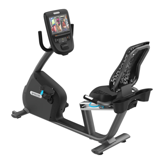
Precor Experience 800 Series Assembly Manual
Line recumbent bike
Hide thumbs
Also See for Experience 800 Series:
- Assembly manual (2 pages) ,
- Getting started manual (2 pages) ,
- Assembly manual (2 pages)
Advertisement
Experience™ Series 800 Line Recumbent Bike (RBK) Assembly Guide
Follow the steps in the order listed in this assembly guide. For more product information,
visit us at www.precor.com.
WARNING
At least two people are required to assemble the equipment. DO
NOT attempt assembly by yourself.
Assembly requirements
Important
Before you fully tighten a fastener, check that its head is flush with the surface of the
equipment. If not, cross-threading may have occurred. DO NOT attempt to rework the assembly as
more damage to the equipment will occur. Instead, contact Customer Support at www. precor.com
We recommend you:
Assemble the equipment close to where you plan to use it.
Assemble the equipment on a solid, flat surface, so that it remains level and stable.
Locate the equipment at least 19.7 inches (0.5 meter) away from walls or furniture on
either side of the equipment, and 19.7 inches (0.5 meter) away from objects behind or in
front of the equipment.
DO NOT move the equipment without assistance.
Required tools
3/8-inch hex wrench
1/4-inch hex wrench
5/32-inch hex wrench
7/16-inch open-end
wrench (2)
#2 Phillips screwdriver
Wire cutter
Assemble the recumbent bike
DANGER
DO NOT attempt to connect electrical power until all assembly procedures are
complete and the console is properly installed.
Before you begin this procedure, retrieve the cables for the console that you plan to install on this exercise bike. The
cables are packed with the console.
Important
DO NOT stretch, crimp, or damage the cables. Cables damaged by improper installation are not covered by the
Precor Limited Warranty.
To begin assembly:
1.
Using a #2 Phillips screwdriver, remove the two self-tapping screws holding the top cover in place. Lift the cover
from its front edge first, then disengage its plastic tabs from the recesses on the rear of the cover (see Figure 1).
2.
Remove the three self-tapping screws holding the rear cover in place, then lift it off (see Figure 2).
3.
Remove the four self-tapping screws holding the left side cover in place, then pull the cover to loosen it. Guide it
around the pedal crank to remove it (see Figure 3).
4. Inside the upright support channel, remove the tape holding the base unit data cable and the heart rate sensor
cable in place.
5.
For touchscreen consoles: Skip to the section, Rewire the bike for a touchscreen console.
For non-touchscreen consoles only: While your assistant holds the upright support over the equipment frame,
thread the base unit data cable and the heart rate sensor cable upward through the support and tape them to the
top of the support. No other cable wiring is required so refer to, Attach the upright support, to continue assembly.
Hardware kit
Component
Socket head screw
(5/16-inch x 3/4-inch)
Flathead machine screw
(1/4-inch x 5/8-inch)
Quantity
Component
4
4
Quantity
Flat washer
4
(5/16-inch)
Upright support
2
mounting screw
Figure 1
Figure 2
Figure 3
Advertisement
Table of Contents

Related Manuals for Precor Experience 800 Series


Summary of Contents for Precor Experience 800 Series
- Page 1 Before you fully tighten a fastener, check that its head is flush with the surface of the equipment. If not, cross-threading may have occurred. DO NOT attempt to rework the assembly as more damage to the equipment will occur. Instead, contact Customer Support at www. precor.com We recommend you: Assemble the equipment close to where you plan to use it.
- Page 2 Then turn the adjustable feet … Raise the equipment Counterclockwise Lower the equipment Clockwise When you are finished adjusting the equipment, recheck for movement and readjust as necessary. 800 Line Recumbent Bike Assembly Guide | P/N 305028-101 rev A, ENU ©Precor Incorporated | December 2016...
Need help?
Do you have a question about the Experience 800 Series and is the answer not in the manual?
Questions and answers