
Summary of Contents for Cortalk uDL1
- Page 1 Configuration and Operation Guide Print Date: August 9, 2018 MOBILTEX® DATA LTD. TITLE: uDL1 Configuration and Operation Guide Calgary, Alberta DOCUMENT NO.: SHEET: REV: www.corTalk.com UDL1-MAN-001 1 of 26 1.07...
- Page 2 Added firmware update procedure. 1.03 April 10, 2013 Updated driver install procedure for new FTDI driver installer. Tony da Costa Updated software install procedure for new composite uDL1/2 media. 1.04 Dec 5, 2013 Updated high-range specifications Tony da Costa 1.05 Nov 24, 2014 Added information for new features in v1.11 firmware.
-
Page 3: Table Of Contents
4.2.1 Configuration Application Installation ....................10 4.2.2 Driver Installation ........................... 11 4.2.3 Adobe Acrobat Reader XI ........................11 uDL1 Configuration and Extraction ....................... 12 4.3.1 uDL1 Communications and Status ......................12 4.3.1.1 Read Config From uDL1 ........................12 4.3.1.2 Write Config To uDL1 ........................12 4.3.1.3... - Page 4 Figure 3 uDL1 Front View ............................... 7 Figure 4 uDL1 USB Cable ............................... 7 Figure 5 uDL1 Analog Cable and Extension Clip Adapters ..................... 7 Figure 6 Programming Application and Driver USB Flash Drive ..................8 Figure 7 Large Alligator Clips ............................8 Figure 8 uDLInstaller Dialog ............................
-
Page 5: Introduction
The uDL1 is a high accuracy, low cost data logger designed specifically for cathodic applications. The device is very simple to use and has a large LCD that can locally verify the readings. Two models of the uDL1 are available. The Basic model has a 500,000 readings measurement memory with a configurable sample rate between 1 second and 12 hours. -
Page 6: General Safety Information
DANGER. Danger indicates an injury hazard immediately accessible as you read the marking. WARNING. Warning indicates an injury hazard not immediately accessible as you read the marking. CAUTION. Caution indicates a hazard to property including the product. MOBILTEX® DATA LTD. TITLE: uDL1 Configuration and Operation Guide Calgary, Alberta DOCUMENT NO.: SHEET: REV: www.corTalk.com... -
Page 7: Udl1 Kit Contents
3 uDL1 Kit Contents The Mobiltex part number for the Basic uDL1 kit is A20A03UDL01. A20A03UDL02 is the part number for the Advanced uDL1 kit. The following items are included in each kit: uDL1 Unit (Basic A15000UDL01 or Advanced A15000UDL02) Figure 3 uDL1 Front View ... -
Page 8: Figure 6 Programming Application And Driver Usb Flash Drive
Figure 6 Programming Application and Driver USB Flash Drive To use a PC to communicate with the uDL1, you will require the media (CD or USB flash drive) that shipped with the uDL1. The media contains drivers and the uDL1 configuration application. If you do not have the media, the contents can be downloaded from the Mobiltex web site at the following URL. -
Page 9: Configuration
Programming Application and Driver Media (CD or USB flash drive) To use a PC to communicate with the uDL1, you will require the media (CD or USB flash drive) that shipped with the uDL1. The media contains drivers and the uDL1 configuration application. If you do not have the media, the contents can be downloaded from the Mobiltex web site at the following URL. -
Page 10: Configuration Application Installation
Figure 10. Click “Close” to complete the installation. Figure 10 uDL1 Configuration Application Installation Complete A shortcut to the configuration application and the uDL1 manual are created in the Windows start menu under the “uDL1 Configuration Application” folder. -
Page 11: Driver Installation
Follow the installation instructions presented by the driver installer application. Figure 11 Driver Installation Screen Once the driver installer completes, you may then plug in the uDL1 through the USB cable into an available USB port on the PC. -
Page 12: Udl1 Configuration And Extraction
4.3.1.1 Read Config From uDL1 The first step in configuring a device is to read in the current settings from the unit. Click on “Read Config From uDL1”. The “Link Status” field will briefly show “Busy” as the current configuration parameters are read from the uDL1. After the link status returns to “Idle”, you will see the configuration settings currently in the uDL1. -
Page 13: Firmware
4.3.1.8 Set uDL1 Clock The “Set uDL1 Clock” is used to set the clock of the uDL1 from the PC clock. Note that in GPS equipped units, the uDL1 clock will automatically be set from the GPS receiver as soon as a valid GPS time fix is detected. -
Page 14: Reboot Udl1
Delaying the sampling past the settling time will then yield a post-transition reading. This parameter is only useful on advanced uDL1 models. Normally, when not needed, the parameter should be left at the default value of 100ms to minimize battery consumption during unit operation. -
Page 15: Interruption Tracking (Advanced G2 Unit Only)
0 and 250ms. Finally, the ‘UTC Offset’ parameter allows the time base of the uDL1 to be skewed by +/-5s relative to actual UTC time. When using the uDL1 with some other manufacturers’ interruption equipment, it may be necessary to adjust the time base to match the other manufacturers’... -
Page 16: Input Range
The time may be displayed in UTC or local time. Click on the corresponding radio button to select the display time type. For local time, the time zone of the configuration PC is used to select time zone offset for the uDL1 display. -
Page 17: Data Memory Group
The “Extract To Master Data File” button allows extraction of the measurement data from the uDL1 into a CSV file. Prior to clicking this button, ensure that the desired time format is selected. Data may be extracted in UTC (GMT) time, or in local time. -
Page 18: Figure 17 Sample Master Data File
The “Master Data File Split Utility” button invokes a utility function that is used to further process the data from the uDL1 for use in other analysis applications. The function allows a master data file to be split into separate output files for DC, AC, temperature, and DC wave readings. -
Page 19: Figure 19 Data Preview Charts Selection
JPEG, BMP, WBMP, PNG, GIF, SVG or SVGZ formats by selecting the appropriate type in the save file dialog. The current chart view may also be printed by clicking the “Print Chart” button. Figure 20 Sample Data Preview Chart MOBILTEX® DATA LTD. TITLE: uDL1 Configuration and Operation Guide Calgary, Alberta DOCUMENT NO.: SHEET: REV: www.corTalk.com... - Page 20 Data charts can be printed and saved. After the data has been extracted from the uDL1, the data memory on the device may be cleared by clicking the “Clear Memory” button. Note that clearing memory may take up to 30s to complete.
-
Page 21: Operation
The waterproof connector that mates to the uDL1 has an automatic physical locking function. The white arrow on the cable should align with the black arrow on the top graphic overlay of the uDL1. When the cable is inserted it will “click”... -
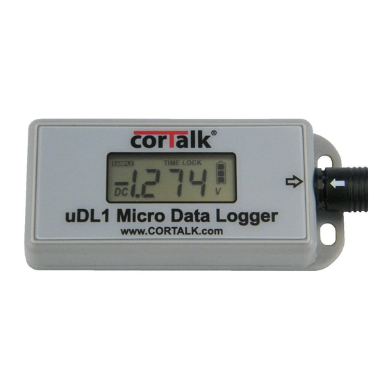
Page 22: Figure 23 Udl1 Front Face
The LCD provides 3 ½ digits of measurement information. When the analog cable is first attached, the uDL1 will enter a real-time measurement display mode for a period of 1 minute. During this time the uDL1 doesn’t store information to memory and it provides real-time measurement data on the LCD which is updated every 2 seconds. -
Page 23: Advanced G1 Model Operation For Interruption Surveys
Note that when this mode is used, the battery life on the uDL1 will vary depending on the value of the sampling delay parameter. With the sampling delay parameter set to 600ms, only 2 days of operation can be expected from a fully charged battery. -
Page 24: Firmware Updates
Figure 24 uDL1 Firmware Update Application Dialog To start the firmware update process, first ensure that the uDL1 is connected to a USB port on the computer. Next, click on the ‘Program Firmware’ button. The application will indicate progress as the firmware is downloaded to the uDL1 (see Figure 25). -
Page 25: Udl Registration
The latest uDL1 software package may be downloaded from the Mobiltex web site at the following URL: http://www.mobiltex.com/cathodic/udl1 uDL Registration Visit www.mobiltex.com/service/registration.html register your uDL to receive notification of free firmware updates. Information provided will be used for the sole purpose of sending notification of firmware updates, and will never be shared or sold. -
Page 26: Udl1 Equipment Specifications
Mobiltex Data Ltd. 3640-26 Street NE Calgary, AB T1Y 4T7 Canada Tel: (403)291-2770 Main Website: http://www.cortalk.com Service Website: http://www.mobiltex.com/service MOBILTEX® DATA LTD. TITLE: uDL1 Configuration and Operation Guide Calgary, Alberta DOCUMENT NO.: SHEET: REV: www.corTalk.com UDL1-MAN-001 26 of 26 1.07...
Need help?
Do you have a question about the uDL1 and is the answer not in the manual?
Questions and answers