Table of Contents
Advertisement
Available languages
Available languages
Quick Links
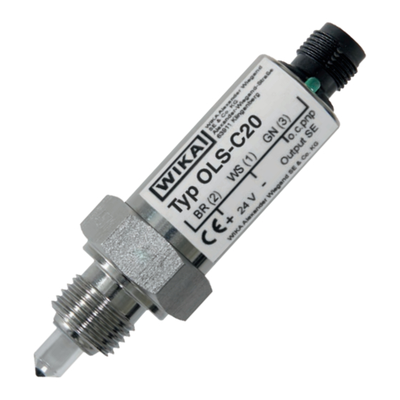
Optoelectronic level switch, model OLS-C20
Optoelektronischer Füllstandsschalter, Typ OLS-C20
Commutateur de niveau opto-électronique, type OLS-C20
Interruptor de nivel optoelectrónic, modelo OLS-C20
Optoelectronic level switch, high-pressure version, model OLS-C20
Operating instructions
Betriebsanleitung
Mode d'emploi
Manual de instrucciones
EN
DE
FR
ES
Advertisement
Chapters
Table of Contents

Related Manuals for WIKA OLS-C20


Summary of Contents for WIKA OLS-C20
- Page 1 Operating instructions Betriebsanleitung Mode d’emploi Manual de instrucciones Optoelectronic level switch, model OLS-C20 Optoelektronischer Füllstandsschalter, Typ OLS-C20 Commutateur de niveau opto-électronique, type OLS-C20 Interruptor de nivel optoelectrónic, modelo OLS-C20 Optoelectronic level switch, high-pressure version, model OLS-C20...
- Page 2 Seite 19 - 34 Mode d'emploi type OLS-C Page 35 - 50 Manual de instrucciones modelo OLS-C20 Página 51 - 65 © 05/2015 WIKA Alexander Wiegand SE & Co. KG All rights reserved. / Alle Rechte vorbehalten. WIKA and KSR are registered trademarks in various countries.
-
Page 3: Table Of Contents
3. Safety 4. Transport, packaging and storage 5. Commissioning, operation 6. Faults 7. Maintenance and cleaning 8. Dismounting, return and disposal 9. Specifications Appendix: EC declaration of conformity Declarations of conformity can be found online at www.wika.com. Operating instructions model OLS-C20... -
Page 4: General Information
The general terms and conditions contained in the sales ■ documentation shall apply. Subject to technical modifications. ■ Further information: ■ - Internet address: www.wika.de / www.wika.com - Relevant data sheet: LM 31.02 Operating instructions model OLS-C20... -
Page 5: Design And Function
2.2 Instrument construction Depending on the switch type, the instruments are fitted with different process connections. These contain a glass prism and the electronics responsible for the evaluation. Operating instructions model OLS-C20... -
Page 6: Safety
3.1 Explanation of symbols WARNING! ... indicates a potentially dangerous situation that can result in serious injury or death, if not avoided. Information ... points out useful tips, recommendations and information for efficient and trouble-free operation. Operating instructions model OLS-C20... - Page 7 The instrument has been designed and built solely for the intended use described here, and may only be used accordingly. The manufacturer shall not be liable for claims of any type based on operation contrary to the intended use. Operating instructions model OLS-C20...
- Page 8 ■ accordance with its intended use. Operating instructions model OLS-C20...
- Page 9 Model OLS-C20 Art.-Nr.13496159 BN (2) WS (1) GN (3) Out- G1/2 24 V Model Article number Electrical connection Before mounting and commissioning the instrument, ensure you read the operating instructions! Operating instructions model OLS-C20...
-
Page 10: Transport, Packaging And Storage
10 mm to the opposite wall. This minimum clearance can vary dependent upon the geometry and surface finish of the wall. Note: with electropolished pipes, the minimum distance to the opposite surface must be a minimum of 20 mm. Operating instructions model OLS-C20... - Page 11 5. Commissioning, operation Installation instructions Horizontal installation Vertical installation Vessel or pipe wall Rubber or metal sealing fitting with sealing face Inclined installation Installation in elongated fitting elongated fitting Insulation Operating instructions model OLS-C20...
-
Page 12: Faults
Glass tip too close to an Increase the distance, no switching of the opposite surface change the mounting output location Glass tip defective Return to the manufacturer Instrument responds Wrong switching function Replace instrument (normally open, normally inversely closed) Operating instructions model OLS-C20... -
Page 13: Maintenance And Cleaning
Residual media in the dismounted instrument can result in a risk to personnel, the environment and equipment. ▶ Rinse or clean the removed instrument. ▶ Sufficient precautionary measures must be taken. Operating instructions model OLS-C20... -
Page 14: Dismounting, Return And Disposal
Wash or clean the dismounted switch before returning it, in order to protect personnel and the environment from exposure to residual media. Information on returns can be found under the heading “Service” on our local website. Operating instructions model OLS-C20... -
Page 15: Specifications
-30 ... +135 °C Ambient temperature -25 ... +70 °C 0 ... 50 bar Pressure range Materials Sensor housing Stainless steel 1.4571 ■ Light guide Fused quartz ■ Packing Graphite/PTFE ■ Case Stainless steel 1.4301 ■ Operating instructions model OLS-C20... - Page 16 Electrical connection PVC cable 3 x 0.14 mm ■ Connector 4-pin series 712, M12 ■ Ingress protection With connector IP65 ■ With cable IP66 ■ For further specifications see WIKA data sheets LM 31.02 and order documentation. Operating instructions model OLS-C20...
-
Page 17: Appendix: Ec Declaration Of Conformity
Appendix: EC declaration of conformity Operating instructions model OLS-C20... - Page 18 Operating instructions model OLS-C20...
- Page 19 1. Allgemeines 2. Aufbau und Funktion 3. Sicherheit 4. Transport, Verpackung und Lagerung 5. Inbetriebnahme, Betrieb 6. Störungen 7. Wartung und Reinigung 8. Demontage, Rücksendung und Entsorgung 9. Technische Daten Anlage: EG-Konformitätserklärung Konformitätserklärungen finden Sie online unter www.wika.de. Betriebsanleitung Typ OLS-C20...
-
Page 20: Allgemeines
Das Fachpersonal muss die Betriebsanleitung vor Beginn aller Arbei- ■ ten sorgfältig durchgelesen und verstanden haben. Es gelten die allgemeinen Geschäftsbedingungen in den Verkaufs- ■ unterlagen. Technische Änderungen vorbehalten. ■ Weitere Informationen: ■ - Internet-Adresse: www.wika.de / www.wika.com - Zugehöriges Datenblatt: LM 31.02 Betriebsanleitung Typ OLS-C20... -
Page 21: Aufbau Und Funktion
Anwendungsbereich ergibt. Als Ausgang steht ein O. C. pnp-Transistor-Schaltausgang oder ein Relais-Schaltausgang zur Verfügung. 2.2 Geräteaufbau Die Geräte sind je nach Schaltertyp mit unterschiedlichen Prozessan- schlüssen ausgestattet. Sie enthalten ein Glasprisma und eine für die Auswertung zuständige Elektronik. Betriebsanleitung Typ OLS-C20... -
Page 22: Sicherheit
... weist auf eine möglicherweise gefährliche Situation hin, die zum Tod oder zu schweren Verletzungen führen kann, wenn sie nicht gemieden wird. Information ... hebt nützliche Tipps und Empfehlungen sowie Informatio- nen für einen effizienten und störungsfreien Betrieb hervor. Betriebsanleitung Typ OLS-C20... - Page 23 Die Schalter dürfen keinen starken mechanischen Belastungen ■ (Stoß, Verbiegen, Vibrationen) ausgesetzt werden. Das Gerät ist ausschließlich für den hier beschriebenen bestimmungs- gemäßen Verwendungszweck konzipiert und konstruiert und darf nur dementsprechend verwendet werden. Ansprüche jeglicher Art aufgrund von nicht bestimmungsgemäßer Verwendung sind ausgeschlossen. Betriebsanleitung Typ OLS-C20...
- Page 24 Bedienpersonal regelmäßig in allen zutreffenden Fragen ■ von Arbeitssicherheit, Erste Hilfe und Umweltschutz unterwiesen wird, sowie die Betriebsanleitung und insbesondere die darin enthal- tenen Sicherheitshinweise kennt. dass das Gerät gemäß der bestimmungsgemäßen Verwendung für ■ den Anwendungsfall geeignet ist. Betriebsanleitung Typ OLS-C20...
- Page 25 SE & Co. KG Alexander-Wiegand-Straße 63911 Klingenberg Model OLS-C20 Art.-Nr.13496159 BN (2) WS (1) GN (3) Out- G1/2 24 V Artikelnummer Elektrische Anschluss Vor Montage und Inbetriebnahme des Gerätes unbedingt die Betriebsanleitung lesen! Betriebsanleitung Typ OLS-C20...
-
Page 26: Transport, Verpackung Und Lagerung
Die Glasspitze sollte nach erfolgter Montage einen Abstand ■ von mindestens 10 mm zu einer gegenüberliegenden Wandung haben. Dieser Mindestabstand kann je nach Geome- trie und Oberflächenbeschaffenheit der Wandung variieren. Achtung: Bei elektropolierten Rohren muss der Mindestabstand zur gegenüberliegenden Fläche mindestens 20 mm betragen. Betriebsanleitung Typ OLS-C20... - Page 27 5. Inbetriebnahme, Betrieb Einbauhinweise Waagerechter Einbau Senkrechter Einbau Behälter- oder Rohrwand Gummi- oder Metalldichtung Stutzen mit Dichtfläche Schräger Einbau Einbau in verlängertem Stutzen verlängerter Stutzen Isolation Betriebsanleitung Typ OLS-C20...
-
Page 28: Störungen
Wechseln der tungsintervalle einführen) Anzeige und Umschalten Glasspitze zu nahe an Entfernung vergrößern, des Ausgangs einer gegenüberliegen- anderen Einbauort wählen den Fläche Glasspitze defekt Rücksendung an den Hersteller Gerät reagiert Falsche Schaltfunktion Gerät austauschen umgekehrt (Schließer, Öffner) Betriebsanleitung Typ OLS-C20... -
Page 29: Wartung Und Reinigung
Körperverletzungen, Sach- und Umweltschäden Eine unsachgemäße Reinigung führt zu Körperverlet- zungen, Sach- und Umweltschäden. Messstoffreste im ausgebauten Gerät können zur Gefährdung von Personen, Umwelt und Einrichtung führen. ▶ Ausgebautes Gerät spülen bzw. säubern. ▶ Ausreichende Vorsichtsmaßnahmen sind zu ergreifen. Betriebsanleitung Typ OLS-C20... -
Page 30: Demontage, Rücksendung Und Entsorgung
Gegebenenfalls muss die Messleitung entspannt werden. 8.2 Rücksendung Ausgebauten Schalter vor der Rücksendung spülen bzw. säubern, um Mitarbeiter und Umwelt vor Gefährdung durch anhaftende Messstoffres- te zu schützen. Hinweise zur Rücksendung befinden sich in der Rubrik „Service“ auf unserer lokalen Internetseite. Betriebsanleitung Typ OLS-C20... -
Page 31: Technische Daten
Optische Anzeige des grüne LED Schaltzustands Auslegungsdaten Mediumstemperatur -30 ... +135 °C Umgebungstemperatur -25 ... +70 °C Druckbereich 0 ... 50 bar Werkstoffe Sensorgehäuse CrNi-Stahl 1.4571 ■ Lichtleiter Quarzglas ■ Packung Graphit/PTFE ■ Gehäuse CrNi-Stahl 1.4301 ■ Betriebsanleitung Typ OLS-C20... - Page 32 = 70 °C) 0,5 A Elektrischer Anschluss PVC-Kabel 3 x 0,14 mm ■ Stecker 4-polig Serie 713, M12 ■ Schutzart Mit Stecker IP65 ■ Mit Kabel IP66 ■ Weitere technische Daten siehe WIKA-Datenblatt LM 31.02 und Bestell- unterlagen. Betriebsanleitung Typ OLS-C20...
-
Page 33: Anlage: Eg-Konformitätserklärung
Anlage: EG-Konformitätserklärung Betriebsanleitung Typ OLS-C20... - Page 34 Betriebsanleitung Typ OLS-C20...
- Page 35 4. Transport, emballage et stockage 5. Mise en service, utilisation 6. Dysfonctionnements 7. Entretien et nettoyage 8. Démontage, retour et mise au rebut 9. Spécifications Annexe : Déclaration de conformité CE Déclarations de conformité disponibles sur www.wika.fr. Mode d‘emploi type OLS-C20...
- Page 36 Les conditions générales de vente mentionnées dans les documents ■ de vente s'appliquent. Sous réserve de modifications techniques. ■ Pour obtenir d'autres informations : ■ - Consulter notre site Internet : www.wika.fr - Fiche technique correspondante : LM 31.02 Mode d‘emploi type OLS-C20...
-
Page 37: Conception Et Fonction
à collecteur ouvert pnp ou à contacts secs relais. 2.2 Exécution de l'instrument Selon le modèle, les instruments sont équipés de différents raccords process. Ceux-ci intègrent le prisme de verre et l'électronique de traitement Mode d‘emploi type OLS-C20... -
Page 38: Sécurité
... indique une situation présentant des risques susceptibles de provoquer la mort ou des blessures graves si elle n‘est pas évitée. Information ... met en exergue les conseils et recommandations utiles de même que les informations permettant d‘assurer un fonctionnement efficace et normal. Mode d‘emploi type OLS-C20... - Page 39 Ces intruments sont conçus et construits exclusivement pour une utilisation conforme à l‘usage prévu décrit ici, et ne doivent être utilisés qu‘à cet effet. Aucune réclamation ne peut être recevable en cas d‘utilisation non conforme à l‘usage prévu. Mode d‘emploi type OLS-C20...
- Page 40 à l‘application en respect de l‘usage ■ prévu de l‘instrument. Mode d‘emploi type OLS-C20...
- Page 41 Art.-Nr.13496159 BN (2) WS (1) GN (3) Out- G1/2 24 V Model Numéro d‘article Raccordement électrique Lire impérativement le mode d‘emploi avant le montage et la mise en service de l‘instrument ! Mode d‘emploi type OLS-C20...
-
Page 42: Transport, Emballage Et Stockage
10 mm par rapport à la paroi opposée. Cette distance minimale peut varier en fonction de la géométrie et la qualité de surface de la paroi. Remarque : dans une tuyauterie électropolie, la distance minimale à la surface opposée doit être au minimum de 20 mm. Mode d‘emploi type OLS-C20... - Page 43 Instructions de montage Montage horizontal Montage vertical Paroi de la cuve ou de la tuyauterie Joint d'étanchéité en caoutchouc ou en métal Raccord avec surface d'étanchéité Montage incliné Montage dans un raccord rallongé Raccord prolongé Isolation Mode d‘emploi type OLS-C20...
-
Page 44: Dysfonctionnements
à l'opposé lieu d'installation Extrémité en verre défectueuse Retourner au fabricant L'instrument réagit de Fonction de commutation Remplacer manière inverse incorrecte (normalement l'instrument ouvert, normalement fermé) Mode d‘emploi type OLS-C20... -
Page 45: Entretien Et Nettoyage
▶ Rincer ou nettoyer avec des moyens appropriés l’instrument qui a été démonté. ▶ Des mesures de sécurité suffisantes doivent être prises. Mode d‘emploi type OLS-C20... -
Page 46: Démontage, Retour Et Mise Au Rebut
Laver et décontaminer le détecteur démonté avant de le renvoyer, afin de protéger le personnel et l‘environnement contre le danger lié aux résidus de fluides adhérents. Des informations relatives à la procédure de retour sont disponibles sur notre site Internet à la rubrique “Services”. Mode d‘emploi type OLS-C20... -
Page 47: Spécifications
-30 ... +135 °C -25 ... +70 °C Température ambiante Gamme de pression 0 ... 50 bar Matériaux Boîtier de la sonde Acier inox 1.4571 ■ Guide de lumière Quartz ■ Garniture Graphite/PTFE ■ Boîtier Acier inox 1.4301 ■ Mode d‘emploi type OLS-C20... - Page 48 3 x 0,14 mm Connecteur Série 4 bornes 712, M12 Indice de protection Avec connecteur IP65 IP66 Avec câble Pour de plus amples spécifications voir fiche technique WIKA LM 31.02 et les documents relatifs à la commande. Mode d‘emploi type OLS-C20...
-
Page 49: Annexe : Déclaration De Conformité Ce
Annexe : Déclaration de conformité CE Mode d‘emploi type OLS-C20... - Page 50 Mode d‘emploi type OLS-C20...
- Page 51 4. Transporte, embalaje y almacenamiento 5. Puesta en servicio, funcionamiento 6. Errores 7. Mantenimiento y limpieza 8. Desmontaje, devolución y eliminación de residuos 9. Datos técnicos Anexo: Declaración de conformidad CE Declaraciones de conformidad puede encontrar en www.wika.es. Manual de instrucciones modelo OLS-C20...
-
Page 52: Información General
Se aplican las condiciones generales de venta incluidas en la ■ documentación de venta. Modificaciones técnicas reservadas. ■ Para obtener más informaciones consultar: ■ - Página web: www.wika.es - Hoja técnica correspondiente: LM 31.02 Manual de instrucciones modelo OLS-C20... -
Page 53: Diseño Y Función
PNP-OC o una salida de relé está disponible como salida. 2.2 Estructura del instrumento Los dispositivos están equipados con diferentes conexiones al proceso, dependiendo del tipo de interruptor. Contienen un prisma de cristal y un sistema electrónico responsable de la evaluación. Manual de instrucciones modelo OLS-C20... -
Page 54: Seguridad
... indica una situación probablemente peligrosa que puede causar la muerte o lesiones graves si no se la evita. Información ... destaca consejos y recomendaciones útiles así como informaciones para una utilización eficiente y libre de errores. Manual de instrucciones modelo OLS-C20... - Page 55 El instrumento ha sido diseñado y construido únicamente para la finalidad aquí descrita y debe utilizarse en conformidad a la misma. No se admite ninguna reclamación debido a una utilización no conforme a lo previsto. Manual de instrucciones modelo OLS-C20...
- Page 56 ■ la aplicación. Manual de instrucciones modelo OLS-C20...
- Page 57 BN (2) WS (1) GN (3) Out- G1/2 24 V Modelo Nº de artículo Conexión eléctrica ¡Es absolutamente necesario leer el manual de instrucciones antes del montaje y la puesta en servicio del instrumento! Manual de instrucciones modelo OLS-C20...
-
Page 58: Transporte, Embalaje Y Almacenamiento
Esta distancia mínima puede variar dependiendo de la geometría y superficie de la pared. Atención: en tubos con electropulido, la distancia mínima a la superficie opuesta debe ser de 20 mm. Manual de instrucciones modelo OLS-C20... - Page 59 Instalación horizontal Instalación vertical Pared del recipiente o del tubo Junta de goma o metal Pieza de conexión con superficie de obturación Instalación diagonal Montaje en la pieza de conexión alargada Pieza de conexión alargada Aislamiento Manual de instrucciones modelo OLS-C20...
-
Page 60: Errores
Punta de cristal defectuosa Enviarla de vuelta al fabricante Función de conmutación Sustituir el Instrumento reacciona de manera contraria errónea (cierre, abertura) instrumento Manual de instrucciones modelo OLS-C20... -
Page 61: Mantenimiento Y Limpieza
Una limpieza inadecuada provoca lesiones corporales, daños materiales y del medio ambiente. Medios residuales en el instrumento desmontado pueden causar riesgos para personas, medio ambiente e instalación. ▶ Lavar o limpiar el dispositivo desmontado. ▶ Tomar adecuadas medidas de precaución. Manual de instrucciones modelo OLS-C20... -
Page 62: Desmontaje, Devolución Y Eliminación De Residuos
Una vez desmontado el interruptor se debe enjuagar y limpiar antes de devolverlo para proteger a las personas y el medio ambiente contra medios residuales de medición. Comentarios sobre el procedimiento de las devoluciones encuentra en el apartado “Servicio” en nuestra página web local. Manual de instrucciones modelo OLS-C20... -
Page 63: Datos Técnicos
Temperatura ambiental -25 ... +70 °C Rango de presión 0 ... 50 bar Materiales Caja del sensor Acero inoxidable 1.4571 ■ Conductor de luz Vidrio de cuarzo ■ Paquete Grafito/PTFE ■ Caja Acero inoxidable 1.4301 ■ Manual de instrucciones modelo OLS-C20... - Page 64 ■ Clavija 4 polos serie 713, M12 ■ Tipo de protección Con clavija IP65 ■ Con cable IP66 ■ Para más datos técnicos véase la WIKA hoja técnica LM 31.02 y la documentación de pedido. Manual de instrucciones modelo OLS-C20...
-
Page 65: Anexo: Declaración De Conformidad Ce
Anexo: Declaración de conformidad CE Manual de instrucciones modelo OLS-C20... - Page 66 Operating instructions model OLS-C20...
- Page 67 Operating instructions model OLS-C20...
- Page 68 KSR Kuebler subsidiaries worldwide can be found online at www.ksr-kuebler.com. WIKA subsidiaries worldwide can be found online at www.wika.com. Manufacturer contact: Sales contact: A division of the WIKA group KSR Kuebler Niveau-Messtechnik AG WIKA Alexander Wiegand SE & Co. KG...
Need help?
Do you have a question about the OLS-C20 and is the answer not in the manual?
Questions and answers