Bose 3-2-1GS Series II Service Manual
Hide thumbs
Also See for 3-2-1GS Series II:
- Owner's manual (80 pages) ,
- Troubleshooting manual (28 pages) ,
- Service manual (94 pages)
Table of Contents
Advertisement
Advertisement
Table of Contents

Subscribe to Our Youtube Channel
Related Manuals for Bose 3-2-1GS Series II


Summary of Contents for Bose 3-2-1GS Series II
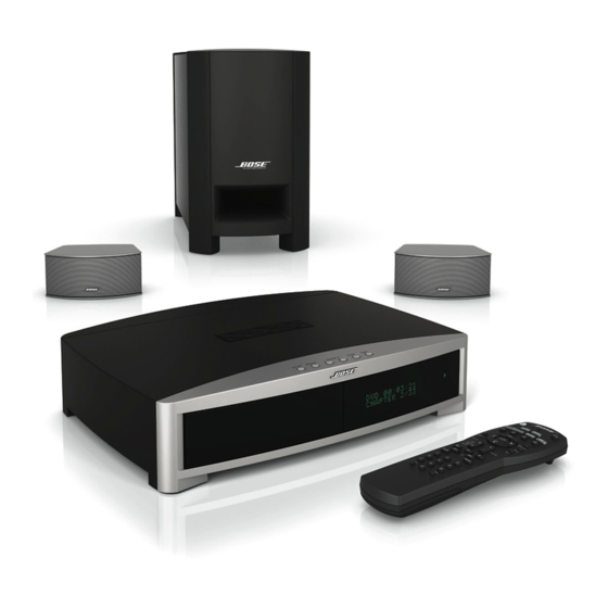
- Page 1 • • • • • Home Entertainment Systems (US and non-US Standard and Premium Versions) • • 1 Series II System • • 1GS Series II System ©2012 Bose Corporation Service Manual Reference Number 273029-SM Rev. 12 Electronic Copy Only...
-
Page 2: Table Of Contents
CONTENTS Safety Information ........................... 3 Warranty ..............................3 Product Description ..........................4 Accessories .............................. 4 Specifications: ............................5-8 Electrostatic Discharge Sensitive (ESDS) Device Handling ............9 Part List Notes ............................9 Packaging Part List, 3•2•1 Series II Home Entertainment System (see Figure 1) ....10-11 Figure 1. -
Page 3: Safety Information
THIS DOCUMENT CONTAINS PROPRIETARY INFORMATION OF BOSE CORPORATION WHICH IS BEING FURNISHED ONLY FOR THE PURPOSE OF SERVICING THE IDENTIFIED BOSE PRODUCT BY AN AUTHORIZED BOSE SERVICE CENTER OR OWNER OF THE BOSE PRODUCT, AND SHALL NOT BE REPRODUCED OR USED FOR ANY OTHER PURPOSE. -
Page 4: Product Description
GS Arrays, silver or graphite, and color matching array cable Bass Module uMusic Remote Control ACCESSORIES The Bose 3•2•1 and 3•2•1GS Series II Home Entertainment Systems shelf speakers are com- patible with Bose mounting accessories, including the UB-20 wall brackets, UFS-20 floor stands and UTS-20 table stands. -
Page 5: Specifications
SPECIFICATIONS System Specifications: Power Rating: US/Canada: 120VAC, 60 Hz, 300W Europe/UK/Aus: 220-240VAC, 50/60 Hz, 300W Japan: 100VAC, 50/60 Hz, 300W Dual Voltage: 115/230VAC, 50/60 Hz, 300W VIDEO, CAB/SAT, AUX Console Inputs: Composite Video, S-Video, Component Video Video Outputs: FM, 75 Ohm F-Connector (PAL, Europe) External Antennas: AM Loop, 2.5 mm mono connector 45 degrees C... - Page 6 SPECIFICATIONS System Specifications (continued): < 400 uVrms, A-weighted Noise when Muted: < 50 mVdc, all channels DC Offset: +/- 1.5 dB for all volume settings Channel Balance: > 40 dB @ 1 kHz, > 30 dB @ 10 kHz, stereo mode Channel Separation: Console Specifications: Compression Formats Supported for discs...
- Page 7 SPECIFICATIONS Console Specifications (continued): Optical S/PDIF Input Characteristics: Sampling Rates Accommodated: 38 kHz, 44.1 kHz and 48 kHz Number of bits recognized: 16, 20 and 24 Error Checking and Handling: Implements full error checking and handling, considering CRC, validity bit, loss of lock, parity error, and bi-phase error.
- Page 8 SPECIFICATIONS Console Specifications (continued): 13 dB nominal / 10 dB limit @ 45 dBf Adjacent Chan Selectivity (200 kHz): Alternate Chan Selectivity (400 kHz): US/Can/Dual/Japan: 70 dB nom/65 dB limit @ 45 dBf Euro/UK/Aus: 75 dB nom/70 dB limit @ 45 dBf Image Rejection: US/Can/Dual/Japan: 45 dB nominal / 40 dB limit...
-
Page 9: Electrostatic Discharge Sensitive (Esds) Device Handling
ELECTROSTATIC DISCHARGE SENSITIVE (ESDS) DEVICE HANDLING This unit contains ESDS devices. We recommend the following precautions when repairing, replacing or transporting ESDS devices: • Perform work at an electrically grounded work station. • Wear wrist straps that connect to the station or heel straps that connect to conductive floor mats. -
Page 10: Packaging Part List, 3•2•1 Series Ii Home Entertainment System (See Figure 1)
274560 GUIDE, OWNERS, 3-LANG 321GSX 298288-001 CARD, REGISTRATION (US/CANADA) 278529-001 SHEET, SLIP, COMPONENT AUDIO 255805 ADDRESS PAGE, BOSE 259434 BAG, POLY, 14.38 x 9.87 x 2 mil 103351 CARD, 3.2.1 UPDATE 268158 DVD, SETUP AND DEMO, 321 II, NTSC 277723... - Page 11 PACKAGING PART LIST 1 Series II Home Entertainment System, continued (see Figure 1) • • 9 10 ARRAYS (ITEM 10) INSIDE EPS FOAM 13 14 15 16 17 18 • • Figure 1. 3 1 Series II Home Entertainment System Packaging View...
-
Page 12: Packaging Part List, 3•2•1 Series Ii System Accessory Kit (See Figure 2)
(EURO, UK, AUS, DUAL RG2 & RG4) CABLE, VIDEO, 6', YL 347428-0010 REMOTE, IR, ADVANCED, 321 II / 321GS II 288579-201 US/CAN (PREPACKAGED REMOTE, BOSE P/N: 327236-0010) REMOTE, IR, ADVANCED, 321 II / 321GS II 288579-202 EURO/UK/AUS REMOTE, IR, 321 II AND 321GS II 288579-203... -
Page 13: Main Part List, 3•2•1 Ii And 3•2•1Gs Ii Console Assembly (See Figure 3)
CABLE, TUNER, 13 COND, FFC 271573-120 CABLE, BUTTON, 135 MM 270914-135 CABLE, DISPLAY, FFC, SHLD, 5 POS, 110 MM 270601-05110 GASKET, EMI (BOSE LINK CONNECTOR) 279058-001 PCB ASSY, MAIN, PROGRAMMED, 286173-107 or STANDARD (US/CANADA, EURO, UK, AUS) 299701-207 PCB ASSY, MAIN, PROGRAMMED,... - Page 14 22 4x 23 6x Figure 3. 3 • • 1 Series II Standard Console Exploded View...
-
Page 15: Main Part List, 3•2•1Gsx Console Assembly (See Figure 4)
MAIN PART LIST 3•2•1GSX Console Assembly (see Figure 4) Item Description Part Number Qty. Note Number COVER, GATE, PREMIUM 282417-002 PRESSURE SENSITIVE ADHESIVE, DIE-CUT 276995-001 312578-001 COVER, CONSOLE, DVD, GRAPHITE SHIELD, UPPER, COVER 270911-001 GASKET, EMI (FM ANTENNA CONNECTOR) 276947-001 PCB ASSY, TUNER (US/CAN, DUAL RG4) 317631-001 or 286177-501... - Page 16 Figure 4. 3 • • 1GSX Series II Premium Console Exploded View...
-
Page 17: Main Part List, Bass Module (See Figure 5)
MAIN PART LIST Bass Modules built before 4/27/09 (see Figure 5a) Item Description Part Number Qty. Note Number FOAM TAPE, .32" W 255202 2 ft. SCREW, TAPP, 8-11 x .5, PAN, ASY, SQ 250817-08 BRACKET, COVER, AMP 255179 SCREW, MACH, SEMS, WSHR, 10-32 x 0.5 264824-08 XFMR, EI, 100V, 50/60HZ (US/CAN, JAPAN) 261278-102... - Page 18 MAIN PART LIST Bass Modules built after 4/27/09 (see Figure 5b) Item Description Part Number Qty. Note Number GASKET, FOAM, .32X12.0X.125 255202 2 ft. SCREW, TAPP, 8-11 x .437, PAN, XRC/S 289388-007 BRACKET, COVER, BASS MODULE 255179 SCREW, TT, 8-32X0.5, PAN, XREC/SQ 289394-008 XFMR, EI, 100V, 50/60HZ, US/CAN/JAPAN 261278-102...
-
Page 19: Main Part List, Standard 3•2•1 Array Assembly (See Figure 6)
1 Array Assembly (see Figure 6) • • Item Description Part Number Qty per Note Number Array GRILLE, ARRAY, GRAPHITE 255196-001 ® NAMEPLATE, BOSE LOGO 255177-001 Note: Only the parts listed above are replaceable. BLACK REAR PANEL TERMINAL STRIP BLACK TWIDDLER DRIVER BLACK ARRAY ENCLOSURE... -
Page 20: Main Part List, 3•2•1 Gs Array Assembly (See Figure 7)
Qty. Note Number TWIDDLER DRIVER ASSY, 50MM 359302-0010 GRILLE, METAL, ARRAY, GRAPHITE 302256-001 GRILLE, METAL, ARRAY, SILVER 302256-003 NAMEPLATE, BOSE, ARRAY 269981-001 FOAM, GRILLE, ARRAY 272036-001 SCREW, HILO, 4-16 x .375, PAN, XREC 181621-06 4 4x 5 8x • •... -
Page 21: Electrical Part Lists
ELECTRICAL PART LIST Console Main PCB Assembly Resistors Reference Description Part Number Note Designator JUMPER, CHIP, 0603 196042 (USED ON UNITS BUILT BEFORE 5/4/07) 33.2K, 0603, 1/10W, 1% 191465-3322 1K, 0603, 1/10W, 1% 191465-1001 9.09K, 0603, 1/10W, 1% 191465-9091 39.2K, 0603, 1/10W, 1% 191465-3922 9.09K, 0603, 1/10W, 1% 191465-9091... -
Page 22: Console Main Pcb Assembly
ELECTRICAL PART LIST Console Main PCB Assembly Resistors (continued) Reference Description Part Number Note Designator R4090 1.00K, 0805, 1/10W, 1% 133625-1001 R4091 1.00K, 0805, 1/10W, 1% 133625-1001 R4099 10K, 0603, 1/10W, 1% 191465-1002 R4100 1.00K, 0805, 1/10W, 1% 133625-1001 R4101 1.00K, 0805, 1/10W, 1% 133625-1001 R4102... - Page 23 ELECTRICAL PART LIST Console Main PCB Assembly Resistors (continued) Reference Description Part Number Note Designator R6317 499 OHM, 0603, 1/10W, 1% 191465-4990 R6319 499 OHM, 0603, 1/10W, 1% 191465-4990 R6500 100 OHM, 0603, 1/10W, 5% 199403-101 R6501 100 OHM, 0603, 1/10W, 5% 199403-101 R6502 10K, 0603, 1/10W, 5%...
- Page 24 ELECTRICAL PART LIST Console Main PCB Assembly Resistors (continued) Reference Description Part Number Note Designator R7013 1K, 0603, 1/10W, 5% 199403-102 R7014 1K, 0603, 1/10W, 5% 199403-102 R7015 4.7K, 0603, 1/10W, 5% 199403-472 R7019 1K, 0603, 1/10W, 5% 199403-102 R7020 2.21K, 0603, 1/10W, 1% 191465-2211 R7021...
- Page 25 ELECTRICAL PART LIST Console Main PCB Assembly Resistors (continued) Reference Description Part Number Note Designator R9201 14K, 0603, 1/10W, 1% 191465-1402 R9202 3.24K, 0603, 1/10W, 1% 191465-3241 R9203 14K, 0603, 1/10W, 1% 191465-1402 R9204 14K, 0603, 1/10W, 1% 191465-1402 R9205 3.24K, 0603, 1/10W, 1% 191465-3241 R9206...
- Page 26 ELECTRICAL PART LIST Console Main PCB Assembly Capacitors Reference Description Part Number Note Designator 0.047uF, 0805, X7R, 50V, 10% 286499-473 0.047uF, 0805, X7R, 50V, 10% 286499-473 0.047uF, 0805, X7R, 50V, 10% 286499-473 330uF, EL, 105C, 50V, 20% 258490-331B24H 0.047uF, 0805, X7R, 50V, 10% 286499-473 2200pF, 0603, X7R, 50V, 10% 191470-222...
- Page 27 ELECTRICAL PART LIST Console Main PCB Assembly Capacitors (continued) Reference Description Part Number Note Designator C3200 0.047uF, 0603, X7R, 25V, 5% 196999-473 C4000 180pF, 0805, COG, 50V, 5% 133622-181 C4001 180pF, 0805, COG, 50V, 5% 133622-181 C4002 180pF, 0805, COG, 50V, 5% 133622-181 C4003 180pF, 0805, COG, 50V, 5%...
- Page 28 ELECTRICAL PART LIST Console Main PCB Assembly Capacitors (continued) Reference Description Part Number Note Designator C4051 220pF, 0805, COG, 50V, 5% 133622-221 C4199 0.10uF, 0603, 16V, 5% 258498-104 C5000 150pF, 0603, COG, 50V, 5% 188454-151 C5002 270pF, 0603, COG, 50V, 5% 188454-271 C5004 150pF, 0603, COG, 50V, 5%...
- Page 29 ELECTRICAL PART LIST Console Main PCB Assembly Capacitors (continued) Reference Description Part Number Note Designator C6708 0.10uF, 0603, 16V, 5% 258498-104 C6710 1000pF, 0603, X7R, 50V, 10% 191470-102 C6807 100pF, 0603, COG, 50V, 5% 188454-101 C6808 100pF, 0603, COG, 50V, 5% 188454-101 C6809 22uF, EL, 85C, 20%, 16V...
- Page 30 ELECTRICAL PART LIST Console Main PCB Assembly Capacitors (continued) Reference Description Part Number Note Designator C7264 0.10uF, 0603, 16V, 5% 258498-104 C7265 0.10uF, 0603, 16V, 5% 258498-104 C7266 0.10uF, 0603, 16V, 5% 258498-104 C7267 0.10uF, 0603, 16V, 5% 258498-104 C7268 0.10uF, 0603, 16V, 5% 258498-104 C7269...
- Page 31 ELECTRICAL PART LIST Console Main PCB Assembly Capacitors (continued) Reference Description Part Number Note Designator C9643 0.10uF, 0603, 16V, 5% 258498-104 C9644 0.10uF, 0603, 16V, 5% 258498-104 C9645 22uF, EL, 85C, 16V, 20% 177902-220C C9646 0.10uF, 0603, 16V, 5% 258498-104 C9647 0.10uF, 0603, 16V, 5% 258498-104...
- Page 32 ELECTRICAL PART LIST Console Main PCB Assembly Diodes Reference Description Part Number Note Designator SCHOTTKY, 40V, 3A, SMB 193847-001 SCHOTTKY, 40V, 3A, SMB 193847-001 D4000 DUAL, SOT-23, BAV99 147239 D4202 DUAL, SOT-23, BAV99 147239 D5000 DUAL, SOT-23, BAV99 147239 D5001 DUAL, SOT-23, BAV99 147239 D5002...
- Page 33 ELECTRICAL PART LIST Console Main PCB Assembly Transistors (continued) Reference Description Part Number Note Designator Q6803 BPLR, N, 40V, 200mA, SOT23 146819 Q6804 BPLR, N, 40V, 200mA, SOT23 146819 Q6805 BPLR, P, 40V, 200mA, SOT23 148596 Q9100 BPLR, N, 40V, 200mA, SOT23 146819 Q9101 BPLR, N, 40V, 200mA, SOT23...
- Page 34 ELECTRICAL PART LIST Console Main PCB Assembly Miscellaneous Reference Description Part Number Note Designator CONN, SMT, LIF, 4 POS, SIDE 255130-004 CONN, SMT, LIF, 4 POS, SIDE 255130-004 CONN, SMT, LIF, 9 POS, SIDE 255130-009 J100 CONN, 13-PIN SOCKET, R-ANGLE 270581-001 J201 CONN, RCA BLOCK, W/GRND FLANGE...
- Page 35 ELECTRICAL PART LIST Console Tuner PCB Assembly Resistors Reference Description Part Number Note Designator R2000 1K, 0603, .1W, 5% 199403-102 R2001 120 OHM, 0603, .1W, 5% 199403-121 R2002 150 OHM, 0603, .1W, 5% 199403-151 R2003 100K, 0603, .1W, 5% 199403-104 R2004 47K, 0603, .1W, 5% 199403-473...
-
Page 36: Console Tuner Pcb Assembly
ELECTRICAL PART LIST Console Tuner PCB Assembly Resistors (continued) Reference Description Part Number Note Designator R2085 3.32K, 0603, .1W, 1% 191465-3321 R2090 100K, 0603, .1W, 5% 199403-104 R2200 2.0K, 0603, .1W, 5% 199403-202 R2201 2.0K, 0603, .1W, 5% 199403-202 R2202 2.0K, 0603, .1W, 5% 199403-202 R2203... - Page 37 ELECTRICAL PART LIST Console Tuner PCB Assembly Capacitors (continued) Reference Description Part Number Note Designator C2015 1uF, EL, 85C, 50V, 20% 177902-010H C2016 .47uF, EL, 85C, 50V, 20% 177902-R47H C2017 22uF, EL, 85C, 20%, 16V 177902-220C C2018 560pF, 0603, X7R, 50V 191470-561 C2019 47uF, EL, 85C, 16V, 20%...
- Page 38 ELECTRICAL PART LIST Console Tuner PCB Assembly Diodes Reference Description Part Number Note Designator D2075 SOT-23, BAV 99 147239 Transistors Reference Description Part Number Note Designator Q2000 P, 50V, 2SA1341 146818 Q2001 BPLR, N, 25V, 30MA, SOT-23 187601-001 Q2002 JFET, N, 20V, 20mA, TO-92 148590-E Q2003 BPLR, N, 40V, 200mA, SOT23 (EURO)
-
Page 39: Bass Module Dsp/Amplifier Pcb Assembly
ELECTRICAL PART LIST Bass Module DSP/Amplifier PCB Assembly Resistors Reference Description Part Number Note Designator 1.00K, 0805, 1/10W, 5% 133626-1025 3.30K, 0805, 1/10W, 5% 133626-3325 10.0K, 0805, 1/10W, 5% 133626-1035 1.00K, 0805, 1/10W, 5% 133626-1025 20.0K, 0805, 1/10W, 5% 133626-2035 1.69K, 0603, 1/10W, 1% 191465-1691 3.32K, 0603, 1/10W, 1%... - Page 40 ELECTRICAL PART LIST Bass Module DSP/Amplifier PCB Assembly Resistors (continued) Reference Description Part Number Note Designator R1001 510 OHM, ARRAY, SMT, 4 POS, 5% 186433-5114 R1005 510 OHM, ARRAY, SMT, 4 POS, 5% 186433-5114 R4200 4.7K, 0603, 1/10W, 5% 199403-472 R4201 75 OHM, 0603, 1/10W, 5% 199403-750...
- Page 41 ELECTRICAL PART LIST Bass Module DSP/Amplifier PCB Assembly Resistors (continued) Reference Description Part Number Note Designator R7201 10K, 0603, 1/10W, 5% 199403-103 R7202 4.7K, 0603, 1/10W, 5% 199403-472 R7203 4.7K, 0603, 1/10W, 5% 199403-472 R7204 47 OHM, 0603, 1/10W, 5% 199403-470 R7205 1M, 0603, 1/10W, 5%...
- Page 42 ELECTRICAL PART LIST Bass Module DSP/Amplifier PCB Assembly Capacitors (continued) Reference Description Part Number Note Designator 470pF, 0603, X7R, 50V, 10% 191470-471 2.2uF, FILM, 100V, 10% 260333-225A 47uF, EL, SMD, 105C, 50V, 20% 255071-470H (USED ON UNITS BUILT AFTER 4/1/05) C150 100uF, EL, 85C, 25V, 20% 177902-101E...
- Page 43 ELECTRICAL PART LIST Bass Module DSP/Amplifier PCB Assembly Capacitors (continued) Reference Description Part Number Note Designator C1002 1000pF, 0603, X7R, 50V, 10% 191470-102 C1003 1000pF, 0603, X7R, 50V, 10% 191470-102 C4000 22uF, EL, 85C, 16V, 20% 177902-220C C4001 .047uF, 0603, X7R, 50V, 10% 191470-473 C4002 .047uF, 0603, X7R, 50V, 10%...
- Page 44 ELECTRICAL PART LIST Bass Module DSP/Amplifier PCB Assembly Capacitors (continued) Reference Description Part Number Note Designator C7009 22pF, 0603, COG, 50V, 5% 188454-220 C7011 150pF, 0603, COG, 50V, 5% 188454-151 C7012 150pF, 0603, COG, 50V, 5% 188454-151 C7108 4700pF, 0603, X7R, 50V, 10% 191470-472 C7109 4700pF, 0603, X7R, 50V, 10%...
- Page 45 ELECTRICAL PART LIST Bass Module DSP/Amplifier PCB Assembly Transistors Reference Description Part Number Note Designator BPLR, N, 40V, 200mA, SOT23 146819 BPLR, N, 40V, 200mA, SOT23 146819 MOSFET, P, 60V, 17A, TO-220 271765-002 BPLR, N, 40V, 200mA, SOT23 146819 Q450 BPLR, N, 50V, 100mA, SOT23 146817 Q451...
-
Page 46: Bass Module Input/Output Pcb Assembly
ELECTRICAL PART LIST Bass Module Input/Output PCB Assembly Capacitors Reference Description Part Number Note Designator 2.2uF, EL, 85C, 50V, 20% 149947-2R2H 2.2uF, EL, 85C, 50V, 20% 149947-2R2H 2.2uF, EL, 85C, 50V, 20% 149947-2R2H 2.2uF, EL, 85C, 50V, 20% 149947-2R2H 4700uF, EL, 105C, 50V, SNAP 261614-472HB3 .01uF, 0805, X7R, 50V, 10% 133623-103... -
Page 47: Disassembly Procedures
DISASSEMBLY PROCEDURES Console Procedures 1. Outer Bezel Removal 1.1 Remove the DVD drawer bezel. To do this, you will need to either apply power to the console and press the EJECT button, or use the manual DVD drawer eject function. This is done by placing a small screwdriver into the front of the slot located in the bottom of the bezel sub-assembly and rapidly... - Page 48 DISASSEMBLY PROCEDURES 2.3 Grasp the console between the top and bottom of the unit, ensuring that you have a good grip on the unit, and carefully flip the console over onto its feet. Lift the top cover straight off. 3. Inner Bezel Sub-assembly Removal (includes Button PCB, IR Receiver PCB and Display PCB) 3.1 Perform procedure 2.
- Page 49 DISASSEMBLY PROCEDURES 4. Tuner PCB Removal 4.1 Perform procedure 2. 4.2 Lift up on the forward edge of the and slide it toward the front of the console until the PCB jacks clear the rear panel. Lift the PCB straight up. 4.3 Unplug the tuner PCB ribbon cable from J6000 on the main PCB.
- Page 50 Re-assembly Notes: 1. Make sure that the RF gasket is in place on top of the Bose Link connector when re- installing the PCB assembly. 2. When installing the main PCB, make sure it is over the locating pin at the front of the...
-
Page 51: Bass Module Procedures
DISASSEMBLY PROCEDURES Bass Module Procedures 1. Rear Enclosure Removal 1.1 Place the bass module on its side. Using a phillips-head screwdriver, remove the four screws that secure the rear enclosure to the bass module cabinet. 1.2 Lift the rear enclosure partially off of the bass module. - Page 52 DISASSEMBLY PROCEDURES 2.4 Carefully lift the main PCB away from the heatsink. Unplug the power transformer secondary harness from the main PCB at J5. Rotate the main PCB clear of the cabinet until it is at about 90 degrees from the heatsink.
-
Page 53: Disassembly Procedures
Repeat this at the other end of the grille. Re-Assembly Note: Align the grille so that the Bose logo is facing the same direction ® as the arrows on the front of the array enclosure. -
Page 54: Test Procedures
TEST PROCEDURES Console Procedures 2. Coaxial Digital Audio Test 2.1 Connect the audio signal generator to CAUTION: The DVD drive mechanism should the input of the analog to S/PDIF converter. not be closed by pushing it shut with no power applied to the console. - Page 55 TEST PROCEDURES 3.5 On the console, select the VIDEO 1 5.2 Connect the video monitor to the source. Press the volume up (+) button on S-VIDEO output of the console. the console for 10 seconds to put it at full volume.
- Page 56 TEST PROCEDURES 7.2 Insert the ABEX TCD-721R test disc into the console CD/DVD tray. Play the defect tracking (scratch) track. Verify that the disc plays properly. The nominal is a 1.6 mm defect, 1.0 mm limit. 7.3 Insert the ABEX TCD-714R test disc into the console CD/DVD tray.
- Page 57 TEST PROCEDURES 8.4 Change the RF frequency to 600 kHz To find the required setting in dBuV emf from (US, Dual) or 603 kHz (Euro, UK, AUS and a given dBf value for an RF generator with a Japan) and re-tune the console to 600 kHz 50 Ohm output impedance use the conver- or 603 kHz (as appropriate).
- Page 58 TEST PROCEDURES Some of the commands in the following 13. FM Stereo Separation tests will automatically set the calibration, 13.1 Inject a 98.1 MHz (83.0 MHz Japan requiring only an external RF signal at the units) RF signal set to 1 kHz left only modu- input of the tuner.
- Page 59 TEST PROCEDURES 16.4 Enter the command “T7” into the 15. AM Stop Level computer. The tuner micro will tune the 15.1 Inject a 1080 kHz RF signal at a level radio, perform the IF Offset processing, and of 57 dBuV emf, 30% modulation at 1 kHz. write the proper offset to EEPROM.
- Page 60 TEST PROCEDURES 19.2 Enter the command TS1A8,0 into the 21. FM Stereo & Force Mono Threshold computer. You will receive an “OK” response from the console, and the unit will tune to 21.1 Inject a 98.1MHz RF signal set to 1kHz the appropriate frequency.
- Page 61 TEST PROCEDURES 23. Hard Drive Self Test (GSX consoles only) 23.1 Issue the TAP command HS (hard disk self test). You will receive an “OK” response. The test will run for two minutes. 23.2 To retrieve the test results, issue the TAP command QHC (query hard drive self test re- sults).
-
Page 62: Bass Module Procedures
TEST PROCEDURES Bass Module Procedures 3. Power Up Test 3.1 Set up the computer to communicate Equipment required: smartspeaker commands with the system • Audio signal generator using the procedures in the appendix of this • dB Meter service manual. •... -
Page 63: Satellite Array Procedures
TEST PROCEDURES 6.4 Select the S/PDIF input by transmitting 4. Air Leak Test the following “SOURCE TYPE” message: 4.1 Apply a 45Hz, 2.0 Vrms sine wave to the 0x0D 0x00 0x03 0x0E Left analog input on the system test cable. PASS: Speaker responds 0x00. - Page 64 TEST PROCEDURES 2. Phase Test 4. Frequency Sweep Test 2.1 Remove the array grille using array 4.1 Jumper both of the drivers in a single disassembly procedure 1. array together. Both center pins of the array connector are negative (-). The two outer 2.2 Observing polarity, apply a +6 Vdc level pins are the positive (+) pins.
- Page 65 • • Figure 8. 3 1 Series II Console Test Setup Diagram...
- Page 66 Figure 9. 3 • • 1 Series II Bass Module Test Setup Diagram...
-
Page 67: Computer Setup Procedure
Computer Setup Procedure Use this procedure to set up your IBM compatible PC for communication with the 3•2•1 system console. 1. Open a terminal window, as shown at right, in either Terminal or Hyperterm, as applicable for the version of Microsoft ®... - Page 68 Computer Setup Procedure (continued) 4. In the properties dialog box, click on the SETTINGS tab and set the controls as shown in the example at right. Notes: 1. Be sure to check "Play sound when connecting or disconnecting". 2. The examples shown on the following pages are for Hyperterminal as used with Windows 2000 Professional.
-
Page 69: Tap Cable Construction
TAP Cable Construction ETAP Cable Construction and Setup You will need to make up an ETAP cable using the dia- gram below. You can build this cable from a Boselink A or B cable and a DB9 connector. You don't need the RCA connectors if you don't want them. -
Page 70: Bass Module Test Cable Construction
Bass Module Test Cable Construction Parts Required: 1 - 321 Series II system cable, Bose part number 269997-001 ® 1 - Female RCA jack, red center, Radio Shack part number 274-337 1 - Female RCA jack, white center, included in Radio Shack part number 274-337... -
Page 71: Console Test Cable Construction
1 - Female 5.5 x 2.1 mm DC Power jack, Radio Shack part number 274-1582 1 - Lifestyle DC power supply, Model DCS91, Bose part number 256764-001 1 - AC line cord, detachable, Bose part number 258491-001. For use with 256764-001. Procedure: 1. -
Page 72: Putting The Console Into Tap Mode
Putting the Console into TAP mode Perform the following steps: 1. Set up your computer’s hyperterminal window as shown in the previous pages. 2. Connect the ETAP cable and RS232 to TTL level shifter to the serial data port on your com- puter. - Page 73 Console TAP Commands (continued) Test Name Command Reply AM/FM Seek Test ‘PT27,xxx,y’ ‘Tuner Stopped: xxxx kHz AM’ or (PT27) where xxx,y ‘Tuner Stopped: xx.x MHz FM’ represents the frequency and where xxx represents the station where the tuner band of the seek stopped.
- Page 74 Console TAP Commands (continued) Test Name Command Reply Setting Console See table below for variants. ‘CV xxx’ ‘OK’ Variant (CV) where xx is a Console Variant Region Code sequence of ASCII Note: This is the characters preferred command representing the for changing region proper console code.
- Page 75 Console TAP Commands (continued) Test Name Command Reply Turn Product Off ‘KP 2E,3,1’ ‘GENERATING KEY PRESS’ (KP) Note: This is a derivative of the “keypress” command: 2E is the key code, 3 is the producer, and 1 is the hold time in ms. The unit must be off to successfully update the FLASH in later test steps.
-
Page 76: Changing The Region Code
Changing the Region Code Load DVD Insert the DVD disc for the region you are changing to into the tray using the EJECT button on the front of the Console. For example, to change a console to region 2, you will need to load a region 2 encoded disc into the tray. -
Page 77: Obtaining System Information From The Media Center Display
APPENDIX Obtaining System Information from the Media Center Display You can obtain system information directly from the media center display by pressing a few buttons. Follow the steps below. - Connect the media center and bass module as instructed in the owner’s guide. - Connect the system to AC mains. - Page 78 APPENDIX Obtaining System Information from the Media Center Display (continued) Console Region Code Setting: Press the ON/OFF button again. You should see the console region code setting, similar to DVD REGION CODE: 1. Console DVD Drive Software Revision and Hardware Information: Press the ON/OFF button again.
-
Page 79: Dvd Lock Options
DVD Lock options The DVD Lock options allow you to restrict viewing of DVD videos with certain ratings. To activate this feature, M edia R emote V ideo A udio C enter L ock C ontrol you need to set a level of restriction and establish a S elect R emote C ontrol to adjust these system password in the DVD Lock section of the System menu. -
Page 80: 3•2•1 Series Ii System Date Of Manufacture Information
DVD Lock options (continued): DVD Lock Bypass If a customer forgets his DVD Lock password, or if you have a system in for repair that is locked and will not let you play a DVD without a password, you can bypass the DVD Lock feature by following the steps below. -
Page 81: Ic Diagrams
IC Diagrams 177984-2, TEA6422 Audio Matrix 193846-001, 3.3V Regulator Pinout Diagram 193846-001, 3.3V Regulator Pin Assignments 193846-001, 3.3V Regulator Block Diagram 186112, Quad Op-Amp... - Page 82 IC Diagrams 184044, 24C01A EEPROM 193858-004, Quad Nand IC 199693, PLL Frequency Synthesizer Pinout 199693, PLL Frequency Synthesizer Block 199693, PLL Frequency Synthesizer Table...
- Page 83 IC Diagrams 254191-003, ADSP21065LKS_264 Digital Signal Processor...
- Page 84 IC Diagrams 254192-003, CODEC 254561-001, AM/FM Tuner 256094-03R3, 3.3V Regulator 254196-001, 3.3V Regulator 258167-09, 9V Regulator...
- Page 85 IC Diagrams 268889-001, 4M-bit Flash Memory 256115-002, 8-bit Binary Counter...
- Page 86 IC Diagrams 256123-001, 3.3V Regulator 258167-09, 9V Regulator 257975, TDA8566TH Power Amplifier 258464-004, 74CHU04 Inverter 260638-18, -33, LD1086 260332-001, 4Mbit Flash Memory D2PAK Regulator...
- Page 87 IC Diagrams 266925-001, CS98200 Digital Signal Processor (DSP)
- Page 88 IC Diagrams 267095-001, SC70 Reset 267336-001, SDRAM, 128Mbit, 166MHz 270223, AK4112B SPDIF Receiver...
- Page 89 IC Diagrams 267548-001, AK4382A Digital to Analog Converter (DAC) 267613-001, 74LCX16245 16-bit Buffer 254182-010, 64 Mbit SDRAM 3.3V...
- Page 90 IC Diagrams 267616-002, CS8415A Digital Audio Receiver 267619-001, Hex Buffer 268457-001, ST72324 TQFP Microprocessor...
-
Page 91: Troubleshooting
Console Troubleshooting Tips Symptom Check for… No power - Check input line cord and/or system cable connected properly. - Check U2 and U17. Console does not initialize - Check that the DVD eject pin is properly aligned with the inner properly bezel plastics. - Page 92 Bass Module Troubleshooting Tips Symptom Check for… Any time you remove the - Clean off all remnants of the old thermal pad (on heatsink, Amplifier / DSP PCB from rectifiers, and FET) and replace thermal pad (267968-075) on the heatsink and re-install heatsink.
-
Page 93: Glossary Of Terms
GLOSSARY OF TERMS Aspect Ratio - The shape of the rectangular picture in a TV set. It is the width of the picture relative to the height. Our standard TV picture, is 4 units wide by 3 units high, or 4:3 in aspect ratio. There are currently two standard TV aspect ratios in the U.S., 4:3 and 16:9. -
Page 94: Service Manual Revision History
SERVICE MANUAL REVISION HISTORY...
Need help?
Do you have a question about the 3-2-1GS Series II and is the answer not in the manual?
Questions and answers
bose 321 home theater system SPEAKER IMPEDANCE /OHMS
The speaker impedance is not specified in the provided information.
This answer is automatically generated