Table of Contents
Advertisement
Advertisement
Table of Contents
Troubleshooting

Related Manuals for Lippert Components ELECTRIC SLIDEOUT SYSTEM


Summary of Contents for Lippert Components ELECTRIC SLIDEOUT SYSTEM
- Page 1 LECTRIC LIDEOUT YSTEM PERATION AND ERVICE ANUAL revB...
-
Page 2: Table Of Contents
ABLE OF ONTENTS SYSTEM……………………………………………..….….. Warning…………………………………..……..Description………………………………..…….. Prior to Operation……………………..……… Preventative Maintenance………..……….. OPERATION…………………………………..…………… Warning............ Extending Slideout Room…..…………. Retracting Slideout Room……..……... Manual Operation………………..………. SERVICE…………………………..………………..……… Adjustment Instructions………..………….. System Components........Syncronizing System........Replacing Actuator........Troubleshooting……………………..……… Wiring Diagram…………………….…..……… Ordering Parts…………..……………………… LIMITED WARRANTY………………..……..…………. Warranty Registration......... -
Page 3: System
Description The Lippert Electric Slideout System is a rack & pinion guide system, utilizing an electric ball screw actuator to move the room assembly. The motor drives the ball screw in a forward and backward motion to drive the slide room in and out. -
Page 4: Prior To Operation
4. Be sure to keep all persons and pets clear of Slideout System during operation. SYSTEM MAINTENANCE The Lippert Electric Slideout System has been static tested to over 4,000 continuous cycles with out any noticeable wear to rotating or sliding parts. It is recommended that when operating in harsh environments (road salt, ice build up, etc.) the moving parts be kept... -
Page 5: Operation
OPERATION WARNING FAILURE TO ACT IN ACCORDANCE WITH THE FOLLOWING MAY RESULT IN SERIOUS PERSONAL INJURY OR DEATH. ALWAYS MAKE SURE THAT THE SLIDEOUT ROOM PATH IS CLEAR OF PEOPLE AND OBJECTS BEFORE AND DURING OPERATION OF THE SLIDEOUT ROOM. ALWAYS KEEP AWAY FROM THE SLIDE RAILS WHEN THE ROOM IS BEING OPERATED. -
Page 6: Manual Operation
Fig.1 MANUAL OPERATION WARNING! Always disconnect battery from system prior to manually operating system. Failure to disconnect battery can cause electricity to backfeed through the motor and cause serious damage to the system as well as void the warranty. The Lippert Electric slide comes with a manual over ride system. Locate the crank extension with pin outside of the chassis main rail as, Fig. - Page 7 MANUAL OPERATION - THROUGH FRAME Through Frame Crank Extension w/ pin Fig. 2 Crank Handle Fig. 3...
- Page 8 MANUAL OPERATION - IN FRAME Motor Hex Head Crank Extension Fig.4 Ratchet Fig.5...
-
Page 9: Service
SERVICE MECHANICAL ROOM ADJUSTMENT Vertical & Horizontal Room Adjustment NOTE: All slideout room adjustments must be performed by certified service technicians. Adjustments made by non-certified persons may void any and all warranty claims. Horizontal adjustment 1. Loosen 2 carriage bolts “A” on each bracket located at the end of each guide tube. - Page 10 MECHANICAL ROOM ADJUSTMENT Bolt “A” Bolt “A” Fig.6 Jam Nut Bolt “B” Fig.7...
- Page 11 MECHANICAL ROOM ADJUSTMENT-CONT. Fig.8 Stop Can Jam Nut-1 Nylock Nut Jam Nut-2 Adjusting room so it seals in the IN position 1. Locate actuator coming through the frame 2. On the end of the actuator there is a threaded shaft mounted to the drive bracket with 3 nuts and a stop can.
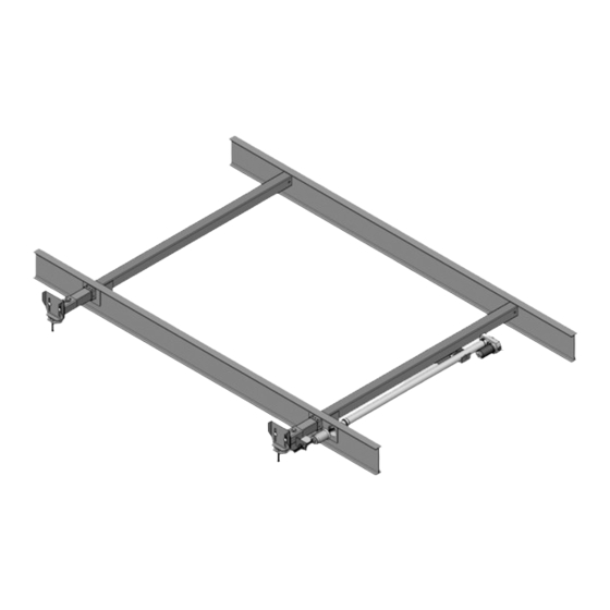
- Page 14 SYNCHRONIZING ROOM TRAVEL Fig.9 The Lippert Electric Slideout System room travel (both sides of the room traveling the same distance) can be adjusted with specially designed synchronizing bracket mounted on the passive slide tube. The passive slide tube is the one that is not powered. The active slide tube is the one that has the cylinder attached.
- Page 15 REMOVING AND REPLACING ACTUATOR To replace actuator: 1. Disconnect manual crank shaft from end of motor assembly (Fig. A). 2. Disconnect motor wires from source. (Fig. A). 3. Take measurements A and B (Fig. B). 4. Remove all jam nuts (3 total) and stop can from threaded shaft on actuator (Fig. B) 5.
-
Page 16: Troubleshooting 1
TROUBLESHOOTING The Lippert Electric Slideout System is only one of four interrelated slideout room system components. These four components are: chassis, room, coach, and Lippert Electric Slideout System. Each one needs to function correctly with the others or misalignment problems will occur. -
Page 17: Wiring Diagram 1
System Troubleshooting Chart The following troubleshooting chart outlines some common problems, their causes and possible corrective actions. When reference is made to “Power Unit” it is referring to the motor and actuator as a complete assembly. All Power Units are shipped from the factory with a serial number and date code, which should be given to the service technician when asking for assistance. - Page 18 TROUBLESHOOTING – MOTOR Before attempting to troubleshoot the Motor, make sure an adequate power source is available. The unit batteries should be fully charged or the unit should be plugged into to A/C service with batteries installed. Do not attempt to troubleshoot the Motor without assuring a full 12V DC charge The following tests require only a DC voltmeter (or DC test light) and a jumper lead.
- Page 19 WIRING DIAGRAM Fig.9 Fig. 10...
-
Page 20: Ordering Parts 2
10. Quantity Please take your coach to an authorized service center for repairs. Systems that have been modified, adjusted, repaired or augmented by a party other than an authorized service center may void any warranty claim with Lippert Components, Inc.
Need help?
Do you have a question about the ELECTRIC SLIDEOUT SYSTEM and is the answer not in the manual?
Questions and answers