Advertisement
Quick Links
Advertisement

Related Manuals for Lippert Components HYDRAULIC SLIDEOUT SYSTEM


Summary of Contents for Lippert Components HYDRAULIC SLIDEOUT SYSTEM
- Page 1 YDRAULIC LIDEOUT YSTEM PERATION AND ERVICE ANUAL...
- Page 2 ABLE OF ONTENTS SYSTEM……………………………………………..….….. Warning…………………………………..……..Description………………………………..…….. Prior to Operation……………………..……… Preventative Maintenance………..……….. OPERATION…………………………………..…………… Warning............Extending Slideout Room….....…………. Retracting Slideout Room…….....……... Auxiliary Operation..…………....………. SERVICE…………………………..………………..……… Filling Procedures........Adjustment Instructions………..………….. Syncronizing System........Replacing Actuator........Troubleshooting……………………..……… Wiring Diagram…………………….…..……… LIMITED WARRANTY………………..……..…………. Warranty Registration.........
-
Page 3: Warning
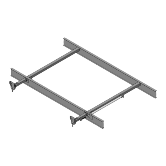
DESCRIPTION The Lippert Hydraulic Slideout System is a rack & pinion guide system, utilizing a hydraulic actuator to move the room assembly. The power unite drives the cylinder rod in a forward and backward motion to drive the slide room in and out. - Page 4 SYSTEM MAINTENANCE The Lippert Hydraulic Slideout System has been static tested to over 4,000 continuous cycles with out any noticeable wear to rotating or sliding parts. It is recommended that when operating in harsh environments (road salt, ice build up, etc.) the moving parts be kept clean and can be washed with mild soap and water.
-
Page 5: Retracting Slideout Room
OPERATION WARNING FAILURE TO ACT IN ACCORDANCE WITH THE FOLLOWING MAY RESULT IN SERIOUS PERSONAL INJURY OR DEATH. ALWAYS MAKE SURE THAT THE SLIDEOUT ROOM PATH IS CLEAR OF PEOPLE AND OBJECTS BEFORE AND DURING OPERATION OF THE SLIDEOUT ROOM. ALWAYS KEEP AWAY FROM THE SLIDE RAILS WHEN THE ROOM IS BEING OPERATED. - Page 6 AUXILIARY OPERATION The Lippert Hydro-Sync Slideout System can be run with auxiliary power devices like electric drills, ratchet wrenches or cordless screwdrivers. In the event of electrical or system failure, this manual method of extending and retracting the slideout room can be used. A standard handheld drill is all that is required. A standard 38"...
- Page 7 Fig. 4 Breather Cap The Lippert Hydraulic Slideout System uses automatic transmission fluid (ATF). Any ATF can be used. A full synthetic or synthetic blend works best such as Dexron III or Mercon 5. For best operation, fill system within ½” of the top when all slideouts are completely retracted.
- Page 8 Bolt “A” Bolt “A” Fig.5 NOTE: Use caution when using prying devise so seals do not become damaged. Vertical adjustment 1. Loosen 2 carriage bolts “A” on each bracket located at the end of each guide tube 2. Loosen jam nut 3.
- Page 9 MECHANICAL ROOM ADJUSTMENT-CONT. Jam Nut-1 2” - 3” FREE TRAVEL Nylock Nut Jam Nut-2 Adjusting room so it seals in the IN position 1. Locate cylinder coming through the frame; 2. On the end of the cylinder there is a threaded shaft mounted to the drive bracket with 3 nuts.
-
Page 10: Replacing Actuator 1
The Lippert Electric Slideout System room travel (both sides of the room traveling the same distance) can be adjusted with specially designed synchronizing bracket mounted on the passive slide tube. The passive slide tube is the one that is not powered. The active slide tube is the one that has the cylinder attached. -
Page 11: Troubleshooting 1
TROUBLESHOOTING CHART The following troubleshooting chart outlines some common problems, their causes and possible corrective actions. When reference is made to a “Power Unit,” the term includes the motor and the actuator as a complete unit. All Power Units are shipped from the factory with a serial number and date code, which should be given to the service technician when asking for assistance. - Page 12 TROUBLESHOOTING – CHECKING FOR BAD CYLINDER 1. Retract (close) the slideout (room) completely. 2. Loosen hose from “E” (extend) port on the manifold of the Power Unit. WARNING- Do not attempt to run room out with the “E” port hose loose. The system will experience RAPID FLUID LOSS.
-
Page 13: Wiring Diagram 1
WIRING DIAGRAM Fig. 11...
Need help?
Do you have a question about the HYDRAULIC SLIDEOUT SYSTEM and is the answer not in the manual?
Questions and answers
Can you manually slide to slide out out on a snowbird SE