Table of Contents
Advertisement
Quick Links
Operators Manual
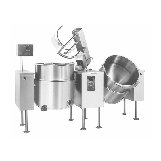
Electric Floor Model Mixers
MODELS:
MKEL-40-T, MKEL-60-T, MKEL-80-T, MKEL-100-T
TMKEL-40-T, TMKEL-60-T, TMKEL-80-T, TMKEL-100-T
™
Cleveland
Enodis
Installation, Operation & Service
1333 East 179th St., Cleveland, Ohio, U.S.A. 44110
Phone: (216) 481-4900 Fax: (216) 481-3782
Visit our web site at www.clevelandrange.com
SE95013 Rev. 5
Advertisement
Table of Contents

Related Manuals for Cleveland MKEL-40-T


Summary of Contents for Cleveland MKEL-40-T
- Page 1 Installation, Operation & Service Electric Floor Model Mixers MODELS: MKEL-40-T, MKEL-60-T, MKEL-80-T, MKEL-100-T TMKEL-40-T, TMKEL-60-T, TMKEL-80-T, TMKEL-100-T ™ Cleveland 1333 East 179th St., Cleveland, Ohio, U.S.A. 44110 Phone: (216) 481-4900 Fax: (216) 481-3782 Enodis Visit our web site at www.clevelandrange.com SE95013 Rev. 5...
-
Page 2: For Your Safety
For your safety DANGER Keep clear of pressure Keep hands away from relief discharge. moving parts and pinch points. IMPORTANT Do not fill kettle above Inspect unit daily for recommended level proper operation. marked on outside of kettle. CAUTION Surfaces may be Wear protective equipment extremely hot! Use when discharging hot product. -
Page 3: Installation
Shipping Damage Instructions shown below. VALVE 12" SHIPPING DAMAGE INSTRUCTIONS If shipping damage to the unit is discovered or suspected, observe the following guidelines in (T) MKEL-40-T 22 1/8" 51" 31" preparing a shipping damage claim. (T) MKEL-60-T 22 1/8"... -
Page 4: Moving Unit
Shim as required to make level with center console (front Jack and back) 4"x4" or larger (front and back) Skid Flanged feet Forklift tongs Recommended Installation Procedure MOVING UNIT 1. While still on skid, move unit as close to final 4. -
Page 5: Electrical Service Connections
⇒ D/ Lower bridge. ⇒ E/ Bridge pins should enter pin hole on kettle perfectly, If not return to step 1 and repeat leveling steps. ⇒ F/ Raise bridge and swing to far right (for twin mixers only). ⇒ G/ Repeat steps D and E (for twin mixers only). - Page 6 QUALITY ASSURANCE CHECKLIST Follow this list only after all other installation steps are completed. Some steps require the use of equipment. Follow operating instructions. The following will be performed before the unit is connected to utilities: 1. Visual Examine unit for scratches, dents, or other defects. 2.
-
Page 7: Optional Controls
OPTIONAL CONTROLS Some units may not have the following items to test 13. Meter Complete this test using markings on mixer arm or a measuring strip if there are no markings on the unit. Test the meter at the following values up to capacity (Should be approx. -
Page 8: Operating Instructions
OPERATING INSTRUCTIONS " M . " General Parts Drawing (some parts shown are optional) ITEM # DESCRIPTION FUNCTION Main Power Switch Power switch for unit. Mix/Lift Switch Sets hydraulics to mix or lift mode. Up/Down Switch When unit is in lift mode, mixer bridge can be raised or lowered with this switch. Mixer Speed Control Dial Controls speed of agitators and mixer bridge lift. -
Page 9: Operating Suggestions
Operating the Kettle Operating Suggestions 1. Before turning kettle on, read the Cleveland Range Mixer Kettles are simple and Vacuum/Pressure Gauge (19). The gauges safe to operate. The following tips will allow you to needle should be in the green zone. Once maximize the use of your new mixer. -
Page 10: General Operation
NOTE: Do not fill kettle above recommended level Lifting & Lowering marked on outside of kettle. LIFT Bridge NOTE: The Low Water Indicator Light (Red) (13) should not be lit when kettle is in the upright WARNING- Insure FAUCET position during kettle operation. This light indicates SPOUT (14) is out of way before that the elements have been automatically shut off raising or lowering bridge. -
Page 11: Parameter Settings
Upper DIGITAL WATER Display Locate delivery spout over 2000 desired kettle. METER OPERATING Lower INSTRUCTIONS 1930 Display CONTINUE RESET Turn START switch to "RESET". Note: The digital counter has been preset at the Delivery will start at "0" and stop at factory and should operate satisfactory. - Page 12 Increase Left of the decimal place is the OPERATING MODE CAL 9900 ˚C Cleveland setting (this number CAL 9900 Controls Drawing Range should be flashing). Factory To the right is the FUNCTION NUMBER.
-
Page 13: Cleaning Instructions
CLEANING INSTRUCTIONS CLEANING INSTRUCTIONS CAUTION 1. Turn unit off. SURFACES MAY 2. Remove drain screen (if applicable). Thoroughly BE EXTREMELY HOT! wash and rinse the screen either in a sink or a dishwasher. CARE AND CLEANING 3. Prepare a warm water and mild detergent solution in the unit. -
Page 14: Scraper Blades
SCRAPER BLADES PRODUCT VALVE 1. Remove retaining ring and slide scraper Daily - clean product valve as follows: blades off agitator arm. 2. Place parts in a pan of warm water to soak. KETTLE 3. Clean in a sink, using a warm water and mild detergent solution. -
Page 15: Stainless Steel Equipment Care And Cleaning
STAINLESS STEEL EQUIPMENT CARE AND CLEANING (Suppied courtesy of Nafem. For more information visit their web site at www.nafem.org) Contrary to popular belief, stainless steels ARE susceptible to rusting. 4. Treat your water. Corrosion on metals is everywhere. It is recognized quickly on iron and Though this is not always practical, softening hard water can do much steel as unsightly yellow/orange rust. -
Page 16: Warranty
SERVICE PARTS WARRANTY Our Company supports a worldwide network of In order to preserve the various agency safety certification (UL, NSF, ASME/Ntl. Bd., etc.), only Maintenance and Repair Centers. Contact your factory-supplied replacement parts should be nearest Maintenance and Repair Centre for replacement parts, service,... -
Page 17: Remote Control Assembly
REMOTE CONTROL ASSEMBLY NOTE: See SWITCH INCLUDED WITH ALL SWITCHES. CONFIGURATIONS for applicable contact cartridge/capacitor combinations and part numbers e l a ITEM NO. PART NO. DESCRIPTION QTY. KE53479 Digital Temperature Controller and Indicator .....1 KE53257 Digital Counter . -
Page 18: Main Console Controls
MAIN CONSOLE CONTROLS NOTE: See SWITCH CONFIGURATIONS for applicable contact cartridge/capacitor combinations and part numbers INCLUDED WITH ALL SWITCHES. ITEM NO. PART NO. DESCRIPTION QTY. KE52190 Knob, Speed Control ........1 KE00860 Cable and Bracket, Speed Control (includes items 9 - 13) . -
Page 19: Switch Configuration
SWITCH SPEED CONTROL CONFIGURATION INDEX FAST MIN. Capacitor Contactor Cartridges MOTOR WILL NOT START UNLESS CONTROL IS AT "MIN." LEFT RIGHT KETTLE KETTLE EMERGENCY OFF/AUTO OFF/AUTO STOP HEAT COOL HEAT COOL PART NO. MAIN MIXER LIFT KE52074 KE603208-9 KE603208-8 POWER LIFT DOWN NOTES:... -
Page 20: Hydraulic Components
HYDRAULIC COMPONENTS Scraper Blades: KETTLE SIZE GALLONS QUANTITY Cooling Fan: Fan ..KE54860 22 23 Fan Cover . . . KE601236 Fan Guard . . . KE54861 NOTE: For Hydraulic Hoses order Part No. RT00505 and specify length required ITEM NO. - Page 21 KE51834 Scraper Blades ..........as required KE51875-3 Electric Motor, 3 hp., 208-230/460V .
- Page 22 ELECTRICAL COMPONENT ASSEMBLY THERMAL 15 19 OVERLOAD RELAY 7 17 19 12 18 20 10 11 15 ITEM NO. PART NO. DESCRIPTION QTY. KE50343-7 Component Mounting Plate ........1 KE50753-10 Relays .
- Page 23 MANUAL TILT - 10" CONSOLE ITEM NO. PART NO. DESCRIPTION QTY. KE51730 Tilt Shaft Bearing ..........1 KE50375 Tilt Shaft, Small Gear, 40 to 80 gal.
- Page 24 POWER TILT - 10" CONSOLE...
- Page 25 POWER TILT - 10" CONSOLE ITEM NO. PART NO. DESCRIPTION QTY. KE51007 Micro Switch ........... .2 KE50581 Bridge Rectifier .
- Page 26 KETTLE BOTTOM Element Terminals 21 22...
- Page 27 KETTLE BOTTOM ITEM NO. PART NO. DESCRIPTION QTY. Fl05025 Bleed Vent Elbow ............1 KE50570 Bleed Vent Nut .
- Page 28 WATER METER ASSEMBLY - 18" CONSOLE...
- Page 29 WATER METER ASSEMBLY - 18" CONSOLE ITEM NO. PART NO. DESCRIPTION QTY. FI05058 3/4" Cross ............1 KE02055-2 Steam Valve Modification .
-
Page 30: Inspection And Maintenance Check List
MAINTENANCE INSPECTION AND MAINTENANCE CHECK LIST Cleveland Range equipment requires little preventative maintenance. We do however provide the following chart as a guide line for inspection and maintenance to keep your unit functioning at 100%. MONTHLY INSPECTIONS Item Inspection Item Switches Inspect switches for damage and correct operation. -
Page 31: Hydraulic Oil Replacement Procedure
RE-INSTALLING SPEED HYDRAULIC OIL CONTROL CABLE REPLACEMENT PROCEDURE One of the most important maintenance tasks is to change the hydraulic oil yearly. Under heavy usage the oil should be changed every nine months. It is important to change the oil regularly to prevent its breakdown which leads to the damaging of components. - Page 32 LUBRICATION DISASSEMBLY OF SWITCH ASSEMBLY Lubricate the following parts every three months to insure smooth operation and reduce wear. 1. Place slotted screwdriver MIXER BRIDGE between contactor HOUSING cartridge and cartridge mounting Fig. 1 There are two grease block as shown in nipples on the mixer Fig.1.
-
Page 33: Solenoid Valve Maintenance
SOLENOID VALVE NOTE: It is not necessary to remove the valve from the pipeline for repairs. MAINTENANCE WARNING: Turn off electrical power supply and depressurize valve before making repairs. Cleaning All solenoid valves should be cleaned periodically. The time between cleanings will vary depending on the medium and service conditions. -
Page 34: Coil Replacement
Coil Replacement Valve Reassembly 1. Reassemble in reverse order of disassembly. WARNING: Turn off electrical power supply. Use exploded view for identification and 1. Disconnect coil lead wires and green placement of parts. grounding wire if present. 2. Lubricate all gaskets with DOW CORNING 2. - Page 35 RESERVOIR FILL 3. Pull Pressure Relief Valve (A) open to insure vessel is not pressurized. PROCEDURES 4. Remove Pressure Relief Valve (A). The kettle's water level must be maintained at the 5. Replace Pressure Relief Valve (A) with Street Elbow (B). proper level to submerge the heater elements.
-
Page 36: Calibrating Procedure
CALIBRATING PROCEDURE Each time the mechanism should move freely and be Insure the unit has a vacuum before you begin accompanied by a rapid calibrating procedures. If unit requires venting refer escape of steam. to Kettle Venting Instructions. If valve appears to be Set On-Off Switch/Temperature Control to "10"... -
Page 37: Flushing Procedure
KETTLE JACKET CLEANOUT AND PASSIVATION PROCEDURES The following procedure should be preformed at least once every three years to prevent possible corrosion and ensure the optimum life of the kettle. DANGER: WARNING: WORKING ON MACHINES WITH IMPROPER REFILLING OF KETTLE JACKET WILL POWER COULD RESULT IN SEVERE RESULT IN IRREVERSIBLE DAMAGE TO UNIT ELECTRICAL SHOCK. - Page 38 PRESSURE GAUGE "O" RING REPLACEMENT Cleveland Kettles are designed to withstand adverse operating conditions associated with high volume cooking facilities. To achieve this, internal components are completely sealed from the outside environment. However, if the Pressure Gauge "O" Ring fails or is not replaced with the gauge, damage can result when water penetrates through this area.
-
Page 39: Diagnostic Guide
DIAGNOSTIC GUIDE This section contains servicing information intended for use by Authorized Service Personnel. NOTE 1: If Fault Isolation Procedure is required, be sure to start at step #1. NOTE 2: On table type kettles the entire control mounting panel may be removed from kettle control housing for easier troubleshooting and parts replacement. - Page 40 Measure continuity of ON/OFF switch. Is Go to step #10. it operating properly? Replace defective ON/OFF switch. Unplug control box and measure the Go to step #11. resistance across potentiometer. Is it Replace defective potentiometer. approximately 0 ohms at maximum setting and 50,000 ohms at minimum? Remove edge connector from control Spray contact cleaner on control box...
- Page 41 Remove kettle thermistor and allow to Replace defective thermistor cool. Remove edge connector from control box. Test resistance across edge connector's pins #2 and #7. Is it approximately 100,000 ohms? Turn the potentiometer on the control box Kettle is operating correctly. clockwise to increase the maximum Spray contact cleaner on control operating temperature.
-
Page 42: Spare Parts List
SPARE PARTS LIST ITEM ON. DESCRIPTION QTY. QTY. DOMESTIC OVERSEAS Spare Parts SE50426 Air Filter Element SE50428 "O" Ring for Air Filter KE52895 Air Regulator KE52936 Fuse KE003209-1 Switch Assembly - On/Off - Maintained KE003209-3 Switch Assembly - On/Off/On - Maintained KE003209-6 Switch Assembly - Momentary Spring Return KE003209-7... - Page 43 FLOW PATH FOR HYDRAULIC SYSTEM Hydraulic Cylinder Variable Restrictor Valve Check Secondary 2 Way Valve Hydraulic Solenoid Motor Valve Primary Hydraulic DOWN Motor LIFT Variable Restrictor To Tank Valve 3 Way Solenoid Valve Relief Valve set at 1000 psi Pump To Tank...
Need help?
Do you have a question about the MKEL-40-T and is the answer not in the manual?
Questions and answers