Table of Contents
Advertisement
INSTALLATION
INSTRUCTION
TABLE OF CONTENTS
GENERAL INFORMATION . . . . . . . . . . . . . . . . . . . . . . . 2
UNIT INSTALLATION . . . . . . . . . . . . . . . . . . . . . . . . . . . 3
VENTING . . . . . . . . . . . . . . . . . . . . . . . . . . . . . . . . . . . . . 5
DUCTWORK . . . . . . . . . . . . . . . . . . . . . . . . . . . . . . . . . . 8
APPLICATION . . . . . . . . . . . . . . . . . . . . . . . . . . . . . . . . 9
GAS PIPING . . . . . . . . . . . . . . . . . . . . . . . . . . . . . . . . . 11
AIRFLOW . . . . . . . . . . . . . . . . . . . . . . . . . . . . . . . . . . . 17
OPERATION AND MAINTENANCE . . . . . . . . . . . . . . . 18
TROUBLESHOOTING . . . . . . . . . . . . . . . . . . . . . . . . . 22
FURNACE ACCESSORIES . . . . . . . . . . . . . . . . . . . . . 25
WIRING DIAGRAM . . . . . . . . . . . . . . . . . . . . . . . . . . . . 26
CAUTION:
READ ALL SAFETY GUIDES BEFORE YOU
START TO INSTALL YOUR FURNACE.
SAVE THIS MANUAL
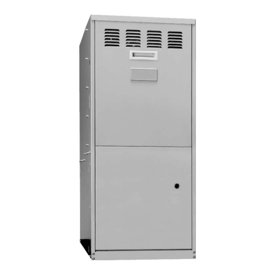
TWO-STAGE ULTRA
MID-EFFICIENCY GAS-FIRED
VARIABLE SPEED FURNACES
Upflow / Horizontal
Models: P*DU - "V" / G8V / L8V
80 To 120 MBH Input
EFFICIENCY
RATING
CERTIFIED
035-17438-001 Rev. A (901)
Advertisement
Table of Contents

Related Manuals for Unitary products group PxDUA12V06401 series


Summary of Contents for Unitary products group PxDUA12V06401 series
-
Page 1: Table Of Contents
INSTALLATION TWO-STAGE ULTRA MID-EFFICIENCY GAS-FIRED INSTRUCTION VARIABLE SPEED FURNACES Upflow / Horizontal Models: P*DU - “V” / G8V / L8V 80 To 120 MBH Input TABLE OF CONTENTS GENERAL INFORMATION ..... . . 2 UNIT INSTALLATION . -
Page 2: General Information
Do not install this furnace in a corrosive or contami- nated atmosphere. Do not install this furnace in a mobile home or recre- ational vehicle. Furnaces shall not be installed directly on carpeting, tile or other combustible material other than wood flooring. Unitary Products Group... -
Page 3: Unit Installation
18" above the garage floor, and located or pro- tected to prevent damage by vehicles. The following must be considered to obtain proper air for combustion and ventilation in confined spaces. Unitary Products Group... - Page 4 Free area or louvers an grilles varies widely; installer should follow louver or grille manufacturer’s instructions. ate conditions requiring special attention to avoid unsatisfac- tory operation of gas appliances. Do not use less than 1/4 in. mesh Unitary Products Group...
-
Page 5: Venting
The chimney must extend at least five feet above the highest equipment draft hood or flue collar. Unitary Products Group... - Page 6 Turn on clothes dryers and any other appliances not connected to the common vent- ing system. Unitary Products Group...
- Page 7 •For altitudes above 2,000 ft., reduce capacity 4% for each 1,000 ft. above sea level. Refer to instruction 035-14461-000. •Wire size based on copper conductors, 60°C, 3% voltage drop. •Continuous return air temperature must not be below 55°F. Unitary Products Group...
-
Page 8: Ductwork
This access cover shall be attached in such a manner as to pre- vent leaks. Unitary Products Group... -
Page 9: Application
If an external mounted filter rack is being used, see tion in the return air system, the ductwork may be directly the instructions provided with that accessory for proper hole attached to the furnace side panel. cut size. Unitary Products Group... - Page 10 This appliance is design certified for line contact for furnaces installed horizontally. The intersection of the furnace top and sides form a line. This line may be in contact with combustible material. Unitary Products Group...
-
Page 11: Gas Piping
With the dis- Minimum 4.5 In. W.C. 11 In. W.C. connect switch in the OFF position, check all wiring against Maximum 13.8 In. W.C. 13.8 In. W.C. the unit wiring label. Also, see the wiring diagram in this instruction. Unitary Products Group... - Page 12 The transformer may Remove the screws and cut wire tie holding excess wiring. provide power for an air conditioning unit contactor. Reposition on the left side of the furnace and fasten using holes provided. Unitary Products Group...
- Page 13 Blower and burner must never be operated without control. the blower panel in place. Electrical supply to the unit is dependent upon the panel that covers the blower compartment being in place and properly positioned. Unitary Products Group...
- Page 14 To decrease outlet pressure, turn the set meter. A typical domestic gas meter usually has a 1/2 or screw counterclockwise. Adjust regulator until pressure 1 cubic foot test dial. shown on manometer matches the pressure specified on the appliance rating plate. Unitary Products Group...
- Page 15 Be sure that the gas valve pressure regulator cap is temperature rise. Take readings of both the return air and the replaced. heated air in the ducts, about six feet from the furnace where they will not be affected by radiant heat. Unitary Products Group...
- Page 16 TXV or solenoid valve. This results in a 45 second off delay at FIGURE 12 : Typical Heat/Cool Speed Tap 75% of the programmed cooing airflow with a 15-second Connections coast to stop. It should be set in the "D" position for a system Unitary Products Group...
-
Page 17: Airflow
From 0.6” to 1.0” static pressure, CFM is reduced the instructions for the electronic air cleaner for further by 2% per 0.1” increase in static. Operation on duct systems details. with greater than 1.0” w.c. external static pressure is not rec- ommended. Unitary Products Group... -
Page 18: Operation And Maintenance
30 seconds then de-energizes to low connected to the “G” terminal of the ignition control to achieve heat speed. HIGH COOL speed (DIP switch number 3 on the ignition con- trol must be in the OFF position). Unitary Products Group... - Page 19 If the timer jumper is gized and a restart of the ignition sequence will begin imme- in the “TIME OFF” position with a single-stage thermostat, the diately. unit will stay in low fire operation. Unitary Products Group...
- Page 20 HEAT FAN DELAY OFF ACTIVATION TRIAL FOR SELECTABLE PERIOD IGNITION 60,90,120,180 SEC. 4 SEC. 7 SEC. NOTE: 1. THIS DIAGRAM SHOWS TWO IGNITION ATTEMPTS 2. TIMING LENGTHS ARE NOT TO SCALE FIGURE 15 : Sequence Timing For Ignitor Control Unitary Products Group...
- Page 21 Clean the flame be brushed and cleaned with a vacuum cleaner. sense rod with steel wool and replace. The procedure for removing the direct drive blower assembly for cleaning is as follows: Unitary Products Group...
-
Page 22: Troubleshooting
The brush must pass • Check for loose or compliant motor mount. around the rear heat exchanger tubes. Vacuum loose scale and dirt from each tube. • Perform motor/control replacement check. Unitary Products Group... - Page 23 Carefully align the locating pin of the control module with REPLACEMENT OF FAILED MOTOR CONTROL the matching motor hole. Replace the 2-1/4” hex head MODULE bolts and tighten snugly. DO NOT OVERTIGHTEN. NOTE: The motor control module may be removed and Unitary Products Group...
- Page 24 µ 0.15 microamps (DC ( If the sensed failure is in the system (external to the control), the LED will flash in the following flash-pause sequences to indicate failure status. Unitary Products Group...
-
Page 25: Furnace Accessories
External Bottom Filter Rack - Cabinet “C” 1PS0313 High Altitude Pressure Switch Kit 1PS0314 High Altitude Pressure Switch Kit 1CK0603 Masonry Chimney Vent Kit for 3” Vents 1CK0604 Masonry Chimney Vent Kit for 4” Vents Please see Price Pages for specific details. Unitary Products Group... -
Page 26: Wiring Diagram
035-17438-001 Rev. A (901) WIRING DIAGRAM NOTE: The furnace’s control system depends on correct polarity of the power supply. Unitary Products Group... - Page 27 035-17438-001 Rev. A (901) SERVICE RECORDS Unitary Products Group...
- Page 28 Subject to change without notice. Printed in U.S.A. 035-17438-001 Rev. A (901) Copyright © by York International Corp. 2001. All rights reserved. Supersedes: 035-17438-001 Rev. A (801) Unitary 5005 Norman Product York Group Drive 73069...
Need help?
Do you have a question about the PxDUA12V06401 series and is the answer not in the manual?
Questions and answers