Table of Contents
Advertisement
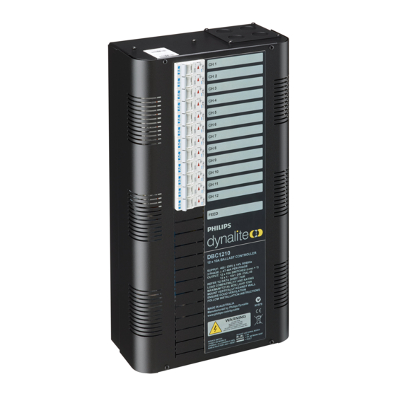
DBC1210
12 x 10A HF Ballast Controller
Installation Manual
Warning..................................................... 2
Features..................................................... 2
Important Safeguards...................................
Internal View............................................... 3
Mounting.................................................... 4
Supply & Load Cable Connections................... 5
Connecting Serial Control Cables....................
Supplied by:
contents
Hardware Controls.......................................
Troubleshooting........................................... 8
2
Speci cation............................................... 8
6
7
Advertisement
Table of Contents

Related Manuals for Philips dynalite DBC1210


Summary of Contents for Philips dynalite DBC1210
-
Page 1: Table Of Contents
DBC1210 12 x 10A HF Ballast Controller Installation Manual contents Warning…………………………………………….. 2 Hardware Controls…………………………….….. Features…………………………………………….. 2 Troubleshooting……………………………………. 8 Speci cation……………………………….………. 8 Important Safeguards…………………………….. Internal View……………………………………….. 3 Mounting…………………………………….……… 4 Supply & Load Cable Connections.……………… 5 Connecting Serial Control Cables……………….. Supplied by:... -
Page 2: Warning
important safeguards Warning – This is a class A product. In a domestic environment this product may cause radio interference in which case the user may be required to take adequate measures. Read Instructions – We recommend that you read this Warning instruction manual prior to commencement of installation. -
Page 3: Internal View
internal view Supply or Load Cable Entry Load Cable Entry Power switch output Manual Circuit Breakers Emergency lighting supply Dimmer control signal 1-10V, DSI or DALI Earth Link 3 phase Supply terminals Channel over ride switch Neutral Link Load Cable Entry Dynet Data Cable Terminal... -
Page 4: Mounting
WMGD Pty Limited trading as Dynalite ABN 33 097 246 92 Unit 6, 691 Gardeners Road Mascot NSW 2020 Australia t +61 8338 9899 f +61 2 8338 9333 dynalite.info@philips.com Philips.com/dynalite... -
Page 5: Supply & Load Cable Connections
supply & load cable connections Supply Cables The supply input terminals are located toward the centre of the enclosure and consist of Earth, Neutral and 3 Phases, which will accept up to 16mm cables. The supply cables should have a capacity of 40A per phase, to allow the device to be loaded to its maximum capacity. -
Page 6: Connecting Serial Control Cables
connecting serial control cables Connect Data Cable in a ‘Daisy Chain’ Determine Your Requirements Serial ports are used to interconnect other dimmers, smart control panels, sensors and AV controllers. Serial port devices can be identified by 4 terminals, labelled: GND, DATA+, DATA-, +VE. Serial Cable Connections There is one RS485 port for DyNet signals, in the form of a RJ12 socket, on the front panel, which is... - Page 7 Diagnostic Information AUX Input - This is a dry contact interface that is active low. The dry contact is connected between the AUX and GND terminals on the DyNet connector strip. The function of the AUX input is programmable. Ensure that the cable length between the dry contact and terminal strip is no longer than 2 metres. Service LED - The Service LED has 3 signalling modes, which are useful for troubleshooting: Blinking slowly (1Hz) = Normal Operation Blinking fast (4Hz) = Network Activity Detected...
-
Page 8: Troubleshooting
Check the following list. If you are still unable to rectify the situation, contact your nearest Dynalite office. A complete list of distributors worldwide can be found on the Internet at: www.philips.com/dynalite Please ensure that you have completed the following prior to calling our technical support department.