Festo SDAS-MHS Manual
Position transmitter
Hide thumbs
Also See for SDAS-MHS:
- Translation of the original instructions (4 pages) ,
- Translation of the original instructions (4 pages)

Subscribe to Our Youtube Channel
Related Manuals for Festo SDAS-MHS


Summary of Contents for Festo SDAS-MHS
- Page 1 SDAS-MHS Position transmitter Description | Function, Operating 8091014 8091014 2018-06 [8091016]...
- Page 2 Translation of the original instructions Festo — SDAS-MHS — 2018-06...
-
Page 3: Table Of Contents
LED display......................22 7.1.2 Reset to factory setting................... 22 Position transmitter operating mode................22 7.2.1 LED display......................22 7.2.2 Reset to factory setting................... 23 Fault clearance......................23 Diagnostics via LED...................... 23 General malfunctions....................24 Disassembly........................ 24 Festo — SDAS-MHS — 2018-06... - Page 4 Technical data......................25 10.1 General..........................25 10.2 IO-Link........................... 26 Festo — SDAS-MHS — 2018-06...
-
Page 5: About This Document
All available documents for the product è www.festo.com/pk. Safety Intended use The position transmitter SDAS-MHS is intended for monitoring the piston stroke. Only use the position transmitter for suitable drives from Festo è www.festo.com/catalogue. Avoid positioning magnetic objects in close proximity to the position transmitter. -
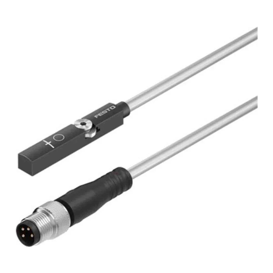
Page 6: Product Overview
1 Connecting cable 5 Marking: centre of the sensing range 2 M8 plug, rotatable 6 Capacitive operating key 3 Red LED: status display 7 Retaining screw 4 Yellow LED: switching status display Fig. 1 Design of SDAS-MHS Festo — SDAS-MHS — 2018-06... -
Page 7: Characteristics
è 4.1 Cylinder switch operating mode. – Position transmitter with IO-Link communication è 4.2 Position transmitter operating mode (IO-Link). In the case of active IO-Link communication (IO-Link master required), the SDAS-MHS switches auto- matically into the position transmitter operating mode. Festo — SDAS-MHS — 2018-06... -
Page 8: Cylinder Switch Operating Mode
– Output signal 24 V DC (PNP or NPN) – Marking on the housing indicates the centre of the sensing range. 1 Electrical output 1 2 Electrical output 2 Fig. 2 Application example: Cylinder switch operating mode Festo — SDAS-MHS — 2018-06... -
Page 9: Cylinder Switch Function
Output signal Hysteresis 1 Teach-in point Fig. 3 Cylinder switch function – The teach-in point is located in the centre of the switching window. – The switching window and hysteresis are preset and cannot be changed. Festo — SDAS-MHS — 2018-06... -
Page 10: Position Transmitter Operating Mode (Io-Link)
Output signal (PDV): direction of increase Output signal (PDV): direction of increase inverted as delivered 1 PDV (position data values) 4 SSC3 2 SSC1 (switching signal channel) 5 SSC4 3 SSC2 Fig. 4 Application example: Position transmitter operating mode Festo — SDAS-MHS — 2018-06... -
Page 11: Cylinder Switch Function
Output signal Hysteresis 1 Teach-in point Fig. 5 Cylinder switch function – The teach-in point is located in the centre of the switching window. – The switching window and hysteresis are preset and cannot be changed. Festo — SDAS-MHS — 2018-06... -
Page 12: Window Comparator
Fig. 6 Window comparator The teach-in points are linked to the window comparator function. – The window width is determined by the position of the teach-in points. – The hysteresis is preset and cannot be changed. Festo — SDAS-MHS — 2018-06... -
Page 13: Hysteresis Comparator
The teach-in points are linked to the hysteresis comparator function. – Teach-in point 1 is the switch-on point, teach-in point 2 is the reset point. – The distance between teach-in point 1 and teach-in point 2 determines the size of the hysteresis. Festo — SDAS-MHS — 2018-06... -
Page 14: Switching Logic, Normally Open (No) And Normally Closed (Nc)
An LED is available to display both switching outputs: – Switching logic NC: the output signal for both switching outputs is AND-gated on the LED display. – Switching logic NO: the output signal for both switching outputs is OR-gated on the LED display. Festo — SDAS-MHS — 2018-06... - Page 15 [or NO: factory setting] SSC 3 Ignored; settings remain in Ignored; setting remains in memory memory SSC 4 Ignored; settings remain in Ignored; setting remains in memory memory Tab. 2 Relationship between the operating modes Festo — SDAS-MHS — 2018-06...
-
Page 16: Installation
Wire colour Allocation Plug Brown (BN) Operating voltage M8x1, 4-pin +24 V DC White (WH) Switching output 2 Blue (BU) 0 V Black (BK) Switching output 1 Tab. 3 Pin allocation of plug connection for cylinder switch operating mode Festo — SDAS-MHS — 2018-06... -
Page 17: Mechanical Installation
3. Push the position transmitter in the direction of the piston until the red LED goes out. 4. Tighten the hexagon socket-head bolts (spanner size: 1.5 mm). – Tightening torque: max. 0.5 Nm Commissioning • Switch on the operating voltage. Ä The position transmitter is ready for operation. Festo — SDAS-MHS — 2018-06... -
Page 18: Cylinder Switch Operating Mode
Press the capacitive operating key 3 times within 3 s. Ä Set-up mode active: yellow and red LEDs flash alternately. If programming is not completed within 60 s of starting set-up mode, the SDAS-MHS automatically switches into the operating mode. Festo — SDAS-MHS — 2018-06... -
Page 19: Set Switching Points
PNP: ON > Flashes > ON – NPN: OFF > Flashes > OFF 3. To change the configuration, press the capacitive operating key 1 time. Ä Change to configuration is stored. Device is ready for operation. Festo — SDAS-MHS — 2018-06... -
Page 20: Menu Structure
Commissioning 6.1.4 Menu structure Fig. 13 Settings using the capacitive operating key (menu structure) Festo — SDAS-MHS — 2018-06... -
Page 21: Position Transmitter Operating Mode
In the position transmitter operating mode, commissioning is carried out in the higher-order controller of the IO-Link master. 1. Load the device description file IODD (è www.festo.com/sp) into the interpreter of the IO-Link master. 2. For general information on the IO-Link specification and for the Smart Sensor profile è www.io-link.com. -
Page 22: Led Display
Parameter Factory setting Switching points None Switching outputs Tab. 7 Factory settings SDAS-MHS Requirement: set-up mode is active. 1. Press the capacitive operating key 10 times. Ä Yellow and red LEDs flash at 2.5 Hz. 2. Press the capacitive operating key. -
Page 23: Reset To Factory Setting
Factory setting SSC channels Not programmed Minimum on the cable side Tab. 9 Factory settings SDAS-MHS The factory settings are reset via IO-Link. Fault clearance Errors during IO-Link operation are displayed on the user interface of the IO-Link master. The IO-Link switching output is not blocked. -
Page 24: General Malfunctions
Tab. 11 Disassembly 1. Switch off the power supply. 2. Disconnect connections from the position transmitter. 3. Undo the hexagon socket-head bolts è Fig.11. 4. Remove the position transmitter from the T-slot of the drive. Festo — SDAS-MHS — 2018-06... - Page 25 0.25 0.05 ≤ switching output Max. output current [mA] Electromechanics Cable length SDAS-MHS- … -0.3-M8: 0.3 SDAS-MHS- … -2.5-LE: 2.5 Nominal conductor " cross section Ambient temperature [°C] –20 +70 … with flexible cable installation Festo — SDAS-MHS — 2018-06...
- Page 26 SSC2 SSC1 data Tab. 15 PDV (Process Data è Variable): Position signal. Data Position switch 4 switch 3 switch 2 switch 1 Type Unsigned Integer BooleanT 1) Switching signal channel Tab. 14 Process data content Festo — SDAS-MHS — 2018-06...
- Page 27 0x0012 (18) Product Name SDAS-MHS- String 64 Byte M40-1L-PNLK- PN-E-0.3-M8 0x0013 (19) Product ID 8063974 String 64 Byte 0x0014 (20) Product Text Position-Trans- String 64 Byte mitter 0x0016 (22) Hardware Revi- REVxy String 64 Byte sion Festo — SDAS-MHS — 2018-06...
- Page 28 Hysteresis UIntT16 0x003E (62) Setpoint 1 216 3784 IntT16 SSC2 … Setpoint 2 216 3784 IntT16 … 0x003F (63) Switchpoint 0 = NO, nor- UIntT8 logic mally open 1 = NC, nor- mally closed Festo — SDAS-MHS — 2018-06...
- Page 29 134 = Cylin- der switch 133 = Win- dow com- parator 3 = Hyster- esis compar- ator Hysteresis UIntT16 0x4002 Setpoint 1 216 3784 IntT16 SSC4 … (16386) Setpoint 2 216 3784 IntT16 … Festo — SDAS-MHS — 2018-06...
- Page 30 Invert the dir- 0 = PDV stand- UIntT8 (12544) ection of the ard: Minimum position value value at cable side 1 = PDV inver- ted: Maximum value at cable side Tab. 18 Inverting the process data Festo — SDAS-MHS — 2018-06...
- Page 31 0x22 (34) Service temporarily not Parameter is not available - device con- accessible due to a trol remote triggered state of the device applica- tion 0x23 (35) Access denied Write access on a read- only parameter Festo — SDAS-MHS — 2018-06...
- Page 32 Parameter inconsisten- cies were found at the end of block parameter transfer, device plaus- ibility check failed 0x82 (130) Application not ready Read or write service is refused due to a tem- porarily unavailable application Festo — SDAS-MHS — 2018-06...
- Page 33 Tab. 20 Error Types Resetting the position transmitter to factory setting Index Sub-Index Access Parameter Values Data type Name 0x0002 (2) Standard Com- 130 = Restore UIntT8 mand Factory Set- tings Tab. 21 Factory setting Festo — SDAS-MHS — 2018-06...
- Page 34 Tab. 22 I-Port: Overview of parameters Byte IO-Link 0x003C 0x003D index Subindex 1 Function Logic Mode – – Byte high high high Default 0x00 0xAF 0x00 0xAF 0x00 0x00 0x00 0x05 values Tab. 23 I-Port: Device specific parameters Festo — SDAS-MHS — 2018-06...
- Page 36 Copyright: Festo AG & Co. KG Ruiter Straße 82 73734 Esslingen Germany Phone: +49 711 347-0 Fax: +49 711 347-2144 Reproduction, distribution or sale of this document or communic- e-mail: ation of its contents to others without express authorization is service_international@festo.com...
Need help?
Do you have a question about the SDAS-MHS and is the answer not in the manual?
Questions and answers