Festo SDAT-MHS Manual
Position transmitter
Hide thumbs
Also See for SDAT-MHS:
- Operating instructions (4 pages) ,
- Operating instructions (2 pages)
Table of Contents
Advertisement
Advertisement
Table of Contents

Related Manuals for Festo SDAT-MHS


Summary of Contents for Festo SDAT-MHS
- Page 1 Position transmitter SDAT-MHS Manual 8080048 2017-11f [8080050]...
- Page 2 Other symbols: Note Material damage or loss of function. Text designations: • Activities which can be carried out in any sequence. 1. Activities which should be carried out in the specified sequence. – General lists. Festo – SDAT-MHS – 2017-11f...
-
Page 3: Table Of Contents
............. Festo – SDAT-MHS – 2017-11f English... - Page 4 ..............Festo – SDAT-MHS – 2017-11f English...
-
Page 5: Product Description
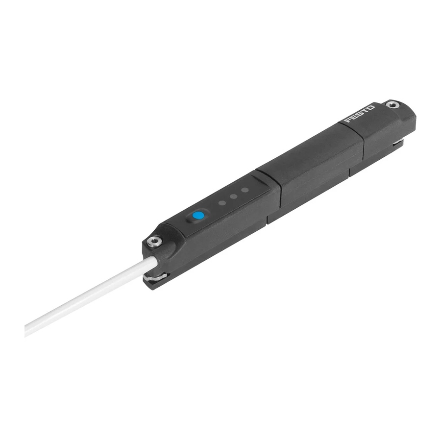
SDAT-MHS Product description For all available product documentation è www.festo.com/pk Overview Connecting cable Green LED: Ready status display Mounting screw Yellow LED: Switching status display Plug M8, rotatable Operating key Red LED: Status display Fig. 1 Control sections and connections... -
Page 6: Function And Application
SDAT-MHS Function and application The position transmitter SDAT-MHS is intended for contactless recording of the piston position of mag netically detectable drives and grippers. It is appropriate for use with Festo drives with T-slot (profile slot 8) as well as round cylinders and tie-rod cylinders with mounting kits. -
Page 7: Analogue Output Function
1) Area è Fig. 2, Area A and C: Red LED illuminated Tab. 2 Output signal, analogue output Note With active IO link communications, the analog output is switched off (output current = 0 mA). Festo – SDAT-MHS – 2017-11f English... -
Page 8: Switching Functions And Switching Logic
0 mm 60 mm 120 mm 160 mm Teach point 1 Teach point 2 Fig. 3 Scaling of the analogue signal (example SDAT-MHS-M160) Switching functions and switching logic 2.2.1 Window comparator Switching travel hysteresis Teach point 1 Teach point 2 Fig. -
Page 9: Cylinder Switch Function
Normally open (NO) and normally closed (NC) contacts The switching logic normally open (NO) is set as standard. The function of the switching output is inver ted through selection of the normally closed function (NC). Festo – SDAT-MHS – 2017-11f English... -
Page 10: Switching Output Operating Mode (Sio)
– Process data: 12 bit for position data and 4 bit for binary channels (è Chapter 10). – Usage of unscreened standard cables of up to 20 m in length is possible. – Device description file IODD for every device length è www.festo.com/sp. – Parameters and functions in accordance with Smart-Sensor profile. -
Page 11: Requirements For Product Use
• Use the product in its original status, without any unauthorised product modifications. • Use the SDAT-MHS only for the suitable drives from Festo (è www.festo.com/catalogue). • Avoid having magnetic bodies near the position transmitter. These could influence the magnetic field and thereby the behaviour of the sensor. - Page 12 Input current 160 mA / max. 4.8 W Analog output 4–20 mA Transistor output max. 30 V DC, 100 mA G.P. Maximum Ambient Temperature 70 °C / 158 °F Enclosure Type Rating Type 1 Festo – SDAT-MHS – 2017-11f English...
-
Page 13: Installation
– The tightening torque for the union nut of the plug: Max. 0.3 Nm. Fig. 7 Circuit diagram Allocation Plug Operating voltage +24 V DC M8x1, 4-pin Analogue output 0…20 mA IO-Link/switching output (C/Q line) Tab. 3 Pin allocation of plug connection Festo – SDAT-MHS – 2017-11f English... -
Page 14: Mechanical
1. Insert the SDAT-MHS into the T-slot of the drive. 2. Move the piston into an end position of the application. 3. Push the SDAT-MHS in the direction of the piston until the red LED goes out. 4. Tighten the mounting screws hand-tight. -
Page 15: Commissioning
1. Press the operating key 3 times within 3 s. è Set-up mode: Green and yellow LED flash simultaneously. Note After entry into the set-up mode, if programming is not completed within 60 s, the SDAT-MHS automatically switches into the operating mode Scale analogue signal Analogue signal Scaled... -
Page 16: Program Switching Output
è Green LED continues to flash, yellow LED flashing at 1 Hz. 5. Move the piston to the 2nd switching point (teach point 2). 6. Press the operating key 1 time. è Switching point 2 is established. è Change into the operating mode. Festo – SDAT-MHS – 2017-11f English... -
Page 17: Set Cylinder Switch Function
è Green LED flashes (2 times briefly in succession within 2 s). 3. Move the piston to the switching point (teach point 1). 4. Press the operating key 1 time. è The switching point is established. è Change into the operating mode. Festo – SDAT-MHS – 2017-11f English... -
Page 18: Set Hysteresis Comparator
è Yellow LED illuminated: Currently set switching logic is NC. è Yellow LED not illuminated: Currently set switching logic is NO. 3. Press the operating key. è The switching logic is inverted. è Change into the operating mode. Festo – SDAT-MHS – 2017-11f English... -
Page 19: Block / Unblock Operating Key
The IO-Link function cannot be set via the operating keys on the device. All settings for set-up, commis sioning and parameterisation are made in the higher-level controller of the IO-Link master. 1. Load the device description file IODD (è www.festo.com/sp) belonging to the device into the interpreter of the IO-Link masters. -
Page 20: Operation
Green LED flashing 3 seconds at 3 Hz while the operating key is pressed: Operating key blocked. Red LED illuminated: Status display. – Piston outside the sensing range. Tab. 4 LED displays in normal operation Festo – SDAT-MHS – 2017-11f English... -
Page 21: Reset Position Transmitter To Factory Setting
è Yellow, green and red LED flash cyclically according to the current configuration (è Tab. 5). Another keystroke ends the interrogation and the SDAT-MHS changes into the operating mode. Without a keystroke, the SDAT-MHS automatically changes into the operating mode after 60 s. -
Page 22: Disassembly
Disassembly 1. Switch off the operating voltage. 2. Separate the connections from the SDAT-MHS. 3. Loosen the mounting screws (è Fig. 8). 4. Take the SDAT-MHS out of the T-slot of the drive. Fault clearance Diagnostics via LED LED display... -
Page 23: General Malfunctions
Remedy short circuit / overload. switch corresponding to output the settings Device defective Replace device. Settings cannot be edited Access protection active Release key (only possible via IO-Link). Tab. 8 Possible malfunctions Accessories Accessories è www.festo.com/catalogue Festo – SDAT-MHS – 2017-11f English... -
Page 24: Technical Data
Immission/emission Ambient temperature [°C] –25…+70 Ambient temperature flexible cable installation [°C] –20…+70 Degree of protection (as per EN 60529) IP65/IP68 (condition IP68: Test duration 24 h) 1) Type-dependent Tab. 9 Technical data SDAT-MHS Festo – SDAT-MHS – 2017-11f English... -
Page 25: Io-Link
2) Max OoR (OoR = Out of range): Maximum value of the sensing range 3) OoR after Power ON: Outside of the sensing range when operating voltage is applied Tab. 12 Range of values of the process data variables (PDV) for the device lengths Festo – SDAT-MHS – 2017-11f English... - Page 26 Access W = write, R = read, R/W = read and write, – = no access 2) Bit 0: Lock parameter write access; Bit1: Lock data storage; Bit3: Lock local user interface (operating key) 3) Festo part number 4) Value defined by user Tab. 14 Service data Festo – SDAT-MHS – 2017-11f English...
- Page 27 2) If access = write, an attempted read access causes the error code 0x8101 to be returned 3) Access also possible through the standard function class 0x8004 “Teach Channel” of the Smart Sensor Profile Tab. 15 System commands Festo – SDAT-MHS – 2017-11f English...
- Page 28 1) Raw data without use of IODD 2) Authorisation group U = user, M = maintenence, S = specialist; access R = read, R/W = read and write 3) Code BDC1…BDC4 è Tab. 17 Tab. 16 Parameters Festo – SDAT-MHS – 2017-11f English...
- Page 29 Error Hardware defective 0x5111 (Dis)appear Warning Voltage too low 0x6320 (Dis)appear Error Parameter error 0x8CA0 (Dis)appear Error Magnetic field too weak, inappropriate drive 0xFF91 SingleShot Notification Data storage upload request Tab. 18 Error codes Festo – SDAT-MHS – 2017-11f English...
-
Page 30: I-Port
IO-Link Index 0x003C 0x003D Subindex Function Logic Mode Byte high high – – high Default value 0x00 0xAF 0x00 0xFA 0x00 0x00 0x00 0x05 1) Parameter coding èTab. 17 Tab. 20 Device Specific Parameters Festo – SDAT-MHS – 2017-11f English... -
Page 31: Appendix
1) Teaching of a position out-of-range (OoR) causes the red LED to flash until the magnet is back in the sensing range (in range). Fig. 13 Settings via the operating key and LED indicators (not IO-Link operation) Festo – SDAT-MHS – 2017-11f English... - Page 32 Copyright: Festo AG & Co. KG Ruiter Straße 82 73734 Esslingen Germany Phone: +49 711 347-0 Fax: +49 711 347-2144 Reproduction, distribution or sale of this document or communica e-mail: tion of its contents to others without express authorization is service_international@festo.com...
Need help?
Do you have a question about the SDAT-MHS and is the answer not in the manual?
Questions and answers