Advertisement
Quick Links
SDAT-MHS-...-SV
Position transmitter
Brief instruction
8154235
2021-08
[8154237]
Translation of the original instructions
© 2022 all rights reserved to Festo SE & Co. KG
1
About this document
1.1
Applicable Documents
All available documents for the product è www.festo.com/sp.
2
Safety
2.1
Intended use
The position transmitter is intended for contactless detection of the piston posi-
tion of magnetic proximity sensing drives and grippers.
– Use the position transmitter only for suitable Festo drives and grippers.
– Do not place magnetic objects in the immediate vicinity of the position trans-
mitter.
2.2
Training of qualified personnel
Work on the product may only be carried out by qualified personnel who can
evaluate the work and detect dangers. The qualified personnel have skills and
experience in dealing with electropneumatic (open-loop) control technology.
2.3
UL/CSA certification
In combination with the UL inspection mark on the product, the information in this
section must also be observed in order to comply with the certification conditions
of Underwriters Laboratories Inc. (UL) for USA and Canada.
UL approval information
Product category code
NRKH, NRKH7
File number
E232949
Considered standards
UL 60947-1, UL 60947-5-2, CSA C22.2 No. 60947-1, CSA C22.2
No. 60947-5-2
UL mark
Ind. Cont. EQ. (Industrial Control Equipment)
2MD1
Tab. 1: UL/CSA approval information
– Technical data and environmental conditions may be subject to change in order
to comply with Underwriters Laboratories Inc. (UL) certification requirements
for the USA and Canada. è 10.3 Technical data for UL/CSA certification
– Only for connection to a NEC/CEC Class 2 supply.
– The device shall be supplied from an isolating transformer having a secondary
listed fuse rated 1 A.
3
Additional information
– Contact the regional Festo contact if you have technical problems
è www.festo.com.
– Accessories and spare parts è www.festo.com/catalogue.
4
4.1
7
Festo SE & Co. KG
6
Ruiter Straße 82
73734 Esslingen
Deutschland
5
+49 711 347-0
www.festo.com
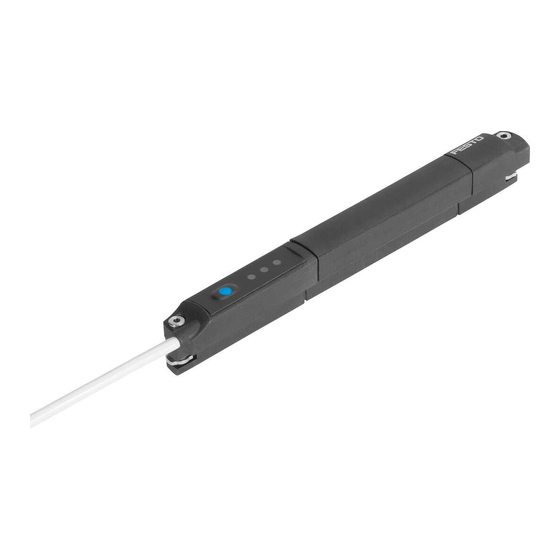
4
Fig. 1: Design of SDAT-MHS
1
2
3
4
4.2
The position transmitter detects the magnetic field of the piston magnet and
continuously senses the piston movement in the sensing range.
The following output signals are available:
– analogue voltage signal: 0 ... 10 V
– programmable switching output: 24 V
– IO-Link communication mode
5
5.1
WARNING
Risk of injury due to electric shock.
• For the electrical power supply, use only PELV circuits in accordance with IEC
60204-1/EN 60204-1 (Protective Extra-Low Voltage, PELV).
• Observe the general requirements of IEC 60204-1/EN 60204-1 for PELV circuits.
• Only use voltage sources that ensure a reliable electric separation from the
mains network in accordance with IEC 60204-1/EN 60204-1.
Fig. 2: Circuit diagram
Pin
1
2
3
4
Tab. 2: Pin allocation of plug connection
Product overview
Design
Connecting cable
Retaining screws
M8 plug, rotatable
Red LED: status indicator
Function
Mounting
Electrical installation
Allocation
Operating voltage +24 V DC
Analogue output 0 ... 10 V
0 V
IO-Link/switching output (C/Q line)
Green LED: ready status display
5
Yellow LED: switching status dis-
6
play
7
Operating key
Plug
M8x1, 4-pin
1
2
3
Advertisement

Related Manuals for Festo SDAT-MHS-SV Series


Summary of Contents for Festo SDAT-MHS-SV Series
- Page 1 The position transmitter is intended for contactless detection of the piston posi- Mounting tion of magnetic proximity sensing drives and grippers. – Use the position transmitter only for suitable Festo drives and grippers. Electrical installation – Do not place magnetic objects in the immediate vicinity of the position trans- WARNING mitter.
- Page 2 Mechanical installation Any mounting position can be used. 10 V 0.5 V 0 mm X mm Fig. 3: Mechanical installation Fig. 4: Characteristic curve of the analogue output Hexagon socket spanner T-slot X = maximum length of the sensing range Signal Description Range...
- Page 3 4. Remove the position transmitter from the T-slot of the drive. Technical data For the complete technical data è Operating instructions SDAT-MHS. 10.1 General SDAT-MHS-... Conformity è www.festo.com/sp Note on materials halogen-free Input signal/measuring element Sensing range [mm] Signal processing Sampling interval typ.
- Page 4 10.2 IO-Link SDAT-MHS-... Protocol version Device V1.1 Profile Smart Sensor Profile Function classes 0x8000:Identification 0x8001:Binary Data Channel 0x8002:Process Data Variable 0x8003:Diagnosis 0x8004:Teach Channel Communication mode COM3 (230.4 kbaud) Process data length IN 2 byte Port class A, 4-pin Device ID 0x000010 0x000011 0x000012...
Need help?
Do you have a question about the SDAT-MHS-SV Series and is the answer not in the manual?
Questions and answers