Table of Contents
Advertisement
OWNER'S
MAHUAL
MODEL NO.
536.884821
Caution:
Read and Follow
All Safety Rules
and Instructions
Before Operating
This Equipment
CRRFr$IRN
5 HORSEPOWER
24" DUAL STAGE
FREE=WHEELIHG TRACK
SNOW THROWER
Optional Electric Start
• Assembly
="Operation
Maintenance
• Service and Adjustments
= Repair Parts
--
[
.................................................
.._....
_
_
_
_
ql U q
IIII1'
ill
SEARS, ROEBUCK AND CO., Chicago, IL 60684 U.S.A.
.....
, ................
i nl
ii
ii
'11
IIII
I
_
......
Z
.......
Advertisement
Table of Contents

Related Manuals for Craftsman 536.884821


Summary of Contents for Craftsman 536.884821
- Page 1 MODEL NO. 536.884821 Caution: Read and Follow All Safety Rules and Instructions Before Operating This Equipment SEARS, ROEBUCK AND CO., Chicago, IL 60684 U.S.A. , ... i nl CRRFr$IRN 5 HORSEPOWER 24" DUAL STAGE FREE=WHEELIHG TRACK SNOW THROWER Optional Electric Start •...
- Page 2 CAUTION: ALWAYS CANNOT CONTACT WIRE WHERE ACCIDENTAL STARTING JUSTING OR MAKING SAFETY STANDARDS REQUIRE RISK OF INJURY. YOUR SNOW THROWER ATTEMPT TO DEFEAT THE FUNCTION ANY CIRCUMSTANCES° BEFORE USE • Read the Owner's Manual carefully. Be thor- oughly fan]iliar with the controls and the proper use of the snow thrower.
- Page 3 Never operate the snow thrower near glass enclosures, automobiles, window wells, drop- offs, and the like without proper adjustment of the snow discharge angre. Keep children and pets away_. ® Never operate the snow thrower at high trans- port speeds on slippery surfaces_ Look behind and use care when backing..
- Page 4 WARRANTY'SERVICE IS AVAILABLEBY RETURNING THE CRAFTSMAN SNOW THROWER TO THE NEAREST SEARS SERVICE CENTER/DEPARTMENT IN THE UNITED STATES. THIS WARRANTY APPLIES ONLY WHILE THIS PRODUCT IS IN USE iN THE UNITED STATES, Thiswan_anty givesyou speciticlegal rights,and youmay also have otherdghts whichmay varyfrom state to state.
-
Page 5: Table Of Contents
SAFETY RULES PRODUCT SPECIFICATIONS CUSTOMER RESPONSIBILITIES WARRANTY TABLE OF CONTENTS INDEX ... ASSEMBLY ... 6-9 OPERATION Adjustmen!: Auger ... Bm! ... Bett Gui_e Cabie Carburelor ... 2 4 Frick;on Wheei Span P!ug ... 24 Track ... 23 Traction and Auger ... Assemoly Cran_ Assembly ShiI!er Lever ... - Page 6 ASSEMBLY lllll ,,,, THIS SNOW TI-IROWER HAS A TRACK DRIVE SYSTEM EQUIPPED TO GIVE YOU FREE-WHEELING If yoursnowthrower must be movedwithoutthe aid of the engine,it willbe easier to pullthe snow thrower backwardby the handles, ratherthan pushing.For detailson how to use the free-wheelingcapability,see the Track Drive/Free-WheelFeature paragraphin the Operation sectionof this manual On startup, the track drive systemmay be tightbut will loosenup as the snowthroweris used Afterfirst use, check the track for tension and adjustif necessary., See the "track Adjustmentparagraphin the Service and...
-
Page 7: Clutch Levers
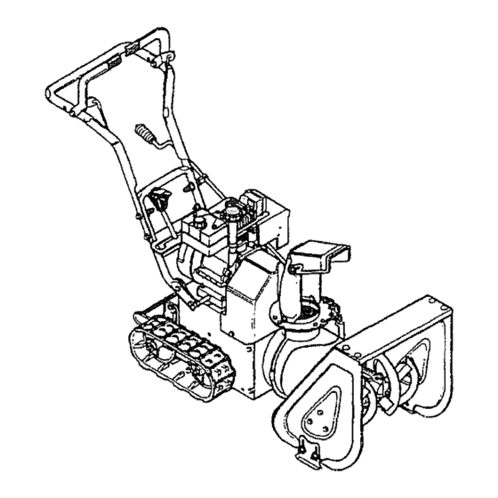
_lll, l llll, Figure1 showsthe snowthmwerintheshipping position. Figure2 shows the snowthrowercomptetety a ssembled, Reference to the righl and left hand side of the snow throweris from the operator'sposition at the handle,, TO REMOVE SNOW THROWER FROM CARTON (See Fig. 1) Removethe staples fromtop of carton. - Page 8 i i illll, ii,i ii ,ll TO INSTALL THE UPPER HANDLE CRANK ASSEMBLY • Remove the screws,flatwashers,to.washers and hexnuts secudngthe shifterplate inthe lowerholes of the lower handle.. • Loosen,t_Jtdo not remove,thescrews,flatwashers, lockwashers, and hex nuts in the upperholesof the lower handle_ •...
- Page 9 TO iNSTALL SHIFTER LEVER KNOB Thread the shifterlever knobontothe threaded end of the shifterlever until itis snug against the hex rut and the lipis pointedtowardthe engine.T_jhten the hexnutagainst thebottomoftheshift leverknob_ (See Fig, 6,) SNIFTER KNOB FIG. 6 TO CHECKJADJUST CLUTCH CONTROL CABLES The controlcables,Fig.
-
Page 10: Snowthrower
SPEED LEVER WEmHr PEDAL HEIGHT ADJUST SEARS FREE-WHEELING SNOW THROWERS conform to the safety standards of the AmericanNational AUGER DRIVE LEVER-Starts and stopsthe augerand impeller(snow gatttering and throwing). "rRACTION DRIVE LEVER - Propelsthe snow thrower forwardand in reverse, SPEED SHIFTER LEVER _ Selects the speed of the snowthrower(6 speedsforwardand 2 speedsreverse). - Page 11 II1,1 I11 iii1[11 i,iir shieldswhile operatingthe snowthrower. We recommend standardsafety glasses available at SEARS Retail or Catalog eyes, whichcan result in severeeye damage. Always wear safety glasses or eye Stores or a wide visionsafety maskfor over your glasses° r=_l "lllqll_ll'lll"...
-
Page 12: Starting
OPERATION 7IJIIIIMII IIIjIIIIIILI] ii I'1 ill TO USE WEIGHT TRANSFER SYSTEM tn hardpacked or heavy snowconditions, c onventional snowthrowerstendtorideup andleaveunevenmounds of snowbehind.Forthese conditions, yournewtracked snow throwerhas a uniqueweighttransfersystem (See Fig,,12) designedto minimize dde4Jp. Theweight transfersystemengaged shifts moreweight to the auger housing,This weight transferkeeps the snow thrower in con*actwith the groundand reduces ride-upon ice and snow°... -
Page 13: Storage
i ii , ,i ,r, FILL GAS: Fill the fuel tank with clean, fresh, unleaded grade autornotive gasoline.Besurethatthecontainer you pour the gasoline from is clean and free from rust or other foreignparticles.Never use gasolinethatmay be stale trom tongperiodsof storage in the container., NOTE: S,,A,,E_ 5 W-30 motor oil may be used to make startingeasier in areaswhere the temperature is 20"... - Page 14 ii_pr_ iiiiii OPERATION iiiiii, i, iii i1,111i PRIMER BUTTON IGNITION CHOKE CONTROL THROTTLE CONTROL FIG, 14 WARM START tf restarting a warm engine after a short shutdown, rotate choketo OFF instead of FULL and do notpush theprimer button.. FROZEN STARTER If the starteris frozen and wiltnot turnengine: •...
-
Page 15: Adjustment 2
MAINTENANCE GENERAL RECOMMENDATIONS The warrantyon thissnowthrowerdoes notcoveritems that have been subjectedto operator abuse or negli- gence,.To receivefull value from the warranty,operator must maintain snowthrower as instructed inthis manual. Some adjustments will need to be made periodically to propedy mainlain your snow thrower, All adjustments inthe Service and Adjustments section of this manual should be checked at feast once each... - Page 16 ENGINE LUBRICATION Check the crankcase oil level (See Fig. 18) before starting the engine and after each five (5) hours of continuous use°Add S.A.E_10W-30 motor oil or equ iva- lenL Tighten fill capldipstick securely each time you check theoil level SA,E_ 5W-30 motor oil may be used to make starting easier in areas where the temperature is 20°...
-
Page 17: Weight Transfer System
$ ... CE AND ADJUST SPARK PLUG WIRE AND AWAY FROM THE PLUG BEFORE MAK- CAUTION: ALWAYS DISCONNECT ING ANY ADJUSTMENTS TO ADJUST SKID HEIGHT This snow thrower is equipped with two height adjust- merit skids, located on the outside of the augerhousing (See Fig. - Page 18 E AND ADJUSTMENTS TO ADJUST THE CLUTCH CONTROL CABLES Pedodicadjustment ofthecables may berequired due to non'natstretch andwearonthe belts Tocheckfor correct adjustment, the controllever mustbe in Ihe fullforward position, r esting on theplasticbumper+Thecontrol cables are correctly adjustedwhenthecenterofthe"Z"Fittingis in the centerofthe holeandthere is nodroopin thecable (See Fig, 22),, If adjustmentis necessary: •...
- Page 19 TO REPLACE BELTS The drive belts on this snow thrower are o! special construction and should be replaced with original equipment belts available from your nearest SEARS Store or Service Center_ You will need the assistanceof a second person while replacing the belts°...
- Page 20 SERVICE AN ,.,DJUSTMENTS TRACTION DRIVE BELT If your snow thrower wilt not move forward, check the tractiondrive belt for wear. tfthe traction drivebelt needs to be replaced,proceed as follows: • Disconnect the spark plug wire. Remove the belt cover (See Fig. 26). Loosenbeltguides (See Fig..
- Page 21 SERVICE ... TO REPLACE FRICTION WHEEL t!thesnowthrowerwillnot move forward, andthe friction wheel is worn or damaged, you need to replace it, as follows: (First allow the engine to cool). ti, t t ,i,ii,t, ttttti, t I ,_ CAUTION: DRAINGASOMNE OUTDOORS AWAY FROM FIRE OR FLAME.
- Page 22 SERVICE AND ADJUSTMENTS ... i ii TO REPLACE AUGER SHEAR BOLT The augers are securedto the auger shaftwith special bolts (See Fig. 35) thatare designedto break (toprotect the machine) if an obiectbecomeslodged in the auger housing. Use of a harder bolt wiUdestroytheprotection providedby the shear bolt.
- Page 23 CE A TO ADJUST CARBURETOR The carburetor (See Fig. 37 and Rg,39) hasbeenpre-set atthe factoryand readjustmentshouldnot benecessary. However, if the carburetordoes need to be adjusted, proceed as follows: Close the high speed adjusting screw by hand., ® Do nol overtighten. Then open it t-1/4 to 1-1t2 turns,, ®...
- Page 24 Touch upall rustedor chippedpaintsurfaces;sane _ightlybeforepainting. • Cover the bare metal parts of the blower'housing auger and[he impellerwithrustprevenlative,such as sprayablelubricant. NOTE: Ayearly checkupor tuneupby a SEARS Service Centerisa goodway toinsure thatyour snow throwerwill providemaximum performanceforthe next season. LUBRICATION OTHER • If possible, store your snow thrower indoors and cover ff to give protection fromdust and dirt.
- Page 25 SERVICE iSERVICE RECORDS Fill In dates as you co_ Aftor plete regular _l_ Rrst 2 Each hours CheckF__j_ OaLave Change _gme Oil i i, ,,_, JJ ... T_jh_n All Screws _ Nuts Check Aug_ Clu'c.hCabLe Adj_nt (See Cable Adius_l LUBRICATION CHART ,...r...,,.;;;, ...
- Page 26 ... TROUBLE SHOOTING POINTS ... TROUBLE CAUSE Otlflcult =tBllng Defective spark#ug Water or d'_ in fuel sys_m Blo_d _e! lineor lowonfuel Engine r_n_ =talk= En=tne=IaUi Unit runningon CHOKE Engln= PJr.aerr=llc_mlly; Water or dirt in fuel system L=_ ofpower Carburetor out o! adjustment Excessive vtbr=tlon Loosepa_.,s;...
- Page 27 NOTES i i i,iii, iii, i,_11 i ii I'H'I...
- Page 28 71071 * Ratwasher. 11/32 in.. 71060 Lockwasher` Split 5/16 In.. 71037 " Nut, Hex. 5/16-18 TI_. 536.884821 Slop, Red Plastic, 5t16 In. Screw. HHC, 5/16-18 x 2 In Spring, Drive C_utch LH Boot, Clutch Spdng Nut, Hex Nyt, 11420 in Screw, HHC, 5116-18 x 3/4 In.
- Page 29 Ring,Retainer 581618 Bolt, Eye Grommet, Eye Bott 308145 Boot, Eye Boll, ChuteCrank Nut, Hex Jam. 3/8-18 Thd. 7t 045 DISCHARGE CHUTE REPAIR PARTS 2 .,t_4 _'__ 536.884821 PART NO. 309344 71046 1162 7052 70993 71060 71037 ; 19 7055 i 20...
- Page 30 Bolt, Carriage, 114-20 x 5/8 Ino 71067 " Flatwasher, 9/32 x 5/8 in. 71059 Lockwasher, Split, 1/4 tn. 71034 " Nut, Hex, 1/4-20Thdo 318582 Auger, Assembly, RH 318581 Auger, Assembly, LH 536.884821 !.A ,01 RE]. ,,,,,,,,,,i,,,,,,,,,,, i ,llJ 9524 73826 301375 302627 302626 306224...
- Page 31 v_,_.rtJq,r- j ;='_I'_F_,I_ ,_q. Oll_lrjvy i rtrtt=/vvlc;rt BELT COVER REPAIR PARTS Ref. It_rnHOo ;_,lu,oo_o,_. REF. PART NO. PART NAME ,,,uu,,, 580773 Cover, Belt 70978 Screw, WaTap, 1/4-20xl/2 71067 * Flatwasher,518Ino * IndicatesStandardHardwarettems_ 31B778_31i4018...
- Page 32 579856 Cable, Clutch 71006 Screw, HHC, 3/8-16 x 1-1/4 in.. 71072 Ratwasher 50793 Pulley, Idler Locknut, Jam, 3/8-16 Thd,. 536.884821 REFo PART NAME PART NO. 579860 Spool, Cable Auger C_utch 71360 Screw, HHC, 1/4-20 x 1-3/4 In 71067 " Flatwasher, .286 x .63 x 065 71035 Nut, Hex Nyl, 1/4-20 Thd.
- Page 33 71060 579857 578733 579855 579854 579932 579861 53715 581264 50677 71063 71015 536.884821 PARTS PART NAME Engine,Craftsman,Model No HSS0*67326K(See Engine Repair Paris list) Screw, HHC, 51t6-18x1.114Inn Loci(washer, S plit,5116x.58x.08 Bracket,Belt Guide Screw, HHC, 5/16-24x5/8 In. Washer, Crankshaft PulleyHalf Belt, TractionDdve Ratwasher, o752xr91x.02...
- Page 34 85501 Bearing Assembly, Trunion 73812 Ratwasher, .50 x I _00x .06 73811 Ring, Retainer 580969 Flatwasher, .680 x 1.12 x ,.06 49562 Bearing, Rolter 536.884821 PARTS PART NO.J PART NAME Key, Square 580961 Pulley, Auger Drive 580965 Wave Washer 580970...
- Page 35 580906 302847 Pin,Cotter 580047 Track,4" WDx 15 Pitch 322424 Pin,Ktick Ring,Retaining 580903 Sprocket, T rack Drive Compact 536.884821 PART NO. PART NAME 70974 Screw, HHC, 1/4-20x 3f4 In. 316863 Bearing,Track 46931 Lockn_Jt, Wd Fi, 1/4-20Thd. 7t 034 Nut,Hex, 1/4-20 Thd_...
- Page 36 Locknut,Wd Fi, 5/16-24 Thd. 303008 Nut,Hex Keps, 1/4-20 Thd_ 302630 Screw,WaTap, 3/8-16x112In. 24274 Seal, Oil 5O304 Bearing,Range 48275 Ratwasher, .752x1,24x 09 581389 Shaft, Auger,24 In. 536.884821 REF. PART NO. 51279 51405 431787 50221 580294 580295 454565 50684 307969 PART NAME...
- Page 37 CRAFTSMAN 24" SNOW THROWER DECALS REAR viEw _ ipA-'_T 302487 302922 3O8766 318509 308768 319033 536.884821 AUGER HOUSING PART' NAME Decal.9"impefler 70141 Decal,DangerAuger 70142 Decal,DangerChute Decal,Dangertr_'lnJctJon Decal,Craftsman Decal,5124Auger Housing Decal,DangerStripe Chute 3902 Decal,TractionDrive Engage 3903 Decal,Auger Drive Engage Decal, Gear Selector...
- Page 38 CRAFTSMAN 24" SNOW THROWER SHIFT YOKE REPAIR PARTS REF_ "Indicates StandardHardwareitems., 536.884821 PARTNAME PART NO. 318463 Rod, Shift 302638 Screw, WdFI, 1/4-20x5/8 In_ 73826 " Locknut,Hex, 1/4-20 Thd. 318486 Nut, HexJam, 112_13 Thd. 304438 Knob,Shift,112-13Thd. 318460 Plate, ShiftLever 579944 Bearing,Range...
- Page 39 CARBURETOR NO, 632107A REWIND STARTER NO. 590646 631615 Throt'Je Shaft E_ Lever As:sy,: ..631767 Throttle Return Spring 631036 Throttle Shutter 650506 Throt_ _ Choke Shutter Screw 632108 Choke Shaft _ Lever As_,_i,. 631815 Choke Shutter 630735 Choke Portioning 631807 Fuel F'_-ting 650417...
- Page 40 CRAFTSMAN 4-CYCLE ENGINE MODEL: HSS0- 67326K IIq II1' Ilql J IIIIII II III1'111111...
- Page 41 CRAFTSMAN 4-CYCLE ENGINE Part Name 33674B Cylinder Assy. (IncL Nee. 2, 20, 72) 26727 Pin, Dowel 30968 Nipple, Pipe 30369 Cap, Off drain 28277 Washer, Flat 31334 Rod, Governor 31510 Lever, Governor 31335 Clamp, Governor lever 650548 Screw, Hex washer hd.,, 8,32 x 5!16 31426 Spring, Extension 326OO...
- Page 42 CRAFTSMAN 4-CYCLE ENGINE Part Part Name 35O72 Cover, Carburetor Screw, Pan hd. Seres, 8-32 x 5116 28371B Plate, Fuel tank mounting 34182 Bracket, Fuel tank 65_05 Screw, Hex hd, w/bellevilie washer, 1/4_20 x tl/16 342A 65O675 Washer, Rat 57O682 Primer Assy_ 321_0C Line, Primer 33344...
- Page 43 ... ii "OTES ... _ ] +L:++L _L+: LH'I"""I'+III "'1' I" I"...
- Page 44 OWNER'S MANUAL MODEL NO. 536.884821 HOW TO ORDER REPAIR PARTS SEARS, ROEBUCK AND CO., Chicago, IL 60684 318533 09104/91 CRAFTSMAN,+ 5 HORSEPOWER 24" DUAL STAGE TRAC-PLUS OPTIONAL ELECTRIC START SNOW THROWER Each SNOW THROWER has its own MODEL NUMBER found on the motor mount frame.