Table of Contents
Advertisement
Advertisement
Table of Contents

Subscribe to Our Youtube Channel
Related Manuals for 3DGence DOUBLE P255


Summary of Contents for 3DGence DOUBLE P255
- Page 1 USER’S MANUAL 3DGence DOUBLE P255...
-
Page 2: Table Of Contents
4.5. Depletion of material during printing ........................... 37 IV FIRST PRINTOUT ..................................37 1. STARTING A READY CODE FROM SD CARD .......................... 37 2. ASSESSMENT OF THE PRINTER OPERATION QUALITY ......................38 page 2 of 62 3DGence DOUBLE P255 | version 09.2018... - Page 3 2.1. Precise axes calibration ..............................49 2.2. Calibration of offsets along X, Y and Z axes ........................51 3. SYSTEM ERRORS AND THEIR REMOVAL ..........................55 IX ENCLOSURE ASSEMBLY ................................57 IX DICTIONARY ....................................59 page 3 of 62 3DGence DOUBLE P255 | version 09.2018...
-
Page 4: I Introduction
(plastic) layer by layer. This plastic is the printer's operating material. The thermoplastic material is used in the form of a filament with a precisely defined diameter, wound on a spool (fig. 1). 3DGence DOUBLE P255 printer uses the filament with the diameter of 1.75 mm. -
Page 5: Symbols
3DGence DOUBLE P255 printer is equipped with two extruders and two hotends. Thanks to this, two materials can be used in one printed model. This solution makes it possible to: • print geometrically complex models that require soluble support structures, •... -
Page 6: The Printer's Backlight Indications
3.2. The printer's backlight indications 3DGence DOUBLE P255 printer is equipped with LED backlight located under the printer's upper plate. The LED backlight illuminates the printout during the printer operation and is also a form of signalling device. The description of all backlight colours and their meanings is given below (table 1). - Page 7 (fig. 2) or wait at least 30 minutes after switching the printer off (e.g. in order to clean or remove the model, change the hotend, etc.) Fig. 2 Temperature indications for: 1, 2. hotends | 3. heatbed page 7 of 62 3DGence DOUBLE P255 | version 09.2018...
-
Page 8: Relocating The Printer
230V/50Hz mains socket (110V version for the USA market), • uninterruptible power supplies (UPS) should be used in order to ensure that the printing process is not stopped in case of instantaneous current decay. page 8 of 62 3DGence DOUBLE P255 | version 09.2018... - Page 9 Fig. 4 The maximum dimensions of the printer taking into account the extreme positions of the heatbed – right side view Fig. 5 The maximum external dimensions of the printer – overview page 9 of 62 3DGence DOUBLE P255 | version 09.2018...
-
Page 10: Specification Of Connection
4.3.1. Specification of connection The electrical characteristics of the 3DGence DOUBLE P255 are shown below (tab.2.3). The connection should be adapted to the given values. ➢ DOUBLE P255 printers with a serial number that begins with the symbol: DOUB (the printer's serial number is located on a sticker located on the back of the printer and it is preceded by the symbol: S/N). -
Page 11: Printer Description
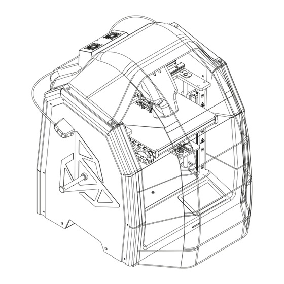
The figures together with the descriptions of the major printer's components are presented below in order to facilitate the operation of 3DGence DOUBLE P255 printer and make it easy to understand the instructions included in the User's Manual (fig. 7-10). Please, refer to the figures and descriptions in order to better understand the 3D printing terminology. - Page 12 Fig. 8 3DGence DOUBLE P255 printer - front isometric projection: 7. Extruder T0 | 8. Extruder T1 | 9. Z axis endstop 10. Z axis breaker | 11. Display | 12. SD card slot Fig. 9 3DGence DOUBLE P255 printer - front isometric projection: 13.
-
Page 13: Kinematic System
Fig. 10 3DGence DOUBLE P255 printer - rear isometric projection: 17. Cable carrier (Z axis) | 18. Mains power supply socket 19. USB port A | 20. USB port B | 21. Printer switch 1.1. Kinematic system The printer works in the Cartesian robot's kinematics. The dual hotend module moves along X axis (to the left - to the right). -
Page 14: Heatbed
1.3. Extruders 3DGence DOUBLE P255 printer is equipped with two material extruding systems (Bowden type extruders) (fig. 13). They are located on the printer's top, behind the dual hotend module. Extruder T0 (Tool 0) is responsible for feeding the base material to hotend T0, while extruder T1 (Tool 1) is responsible for feeding the supporting material to hotend T1. -
Page 15: Dual Hotend Module
1.4. Dual hotend module 3DGence DOUBLE P255 printer is equipped with two hotends installed in the dual hotend module (fig. 14). The module contains the hotend change system for quick assembly and disassembly of hotends having various sizes and purposes. The module contains also the printout cooling system. -
Page 16: Set Of Printer's Accessories
3. USER INTERFACE 3DGence DOUBLE P255 printer is equipped with a 4.3-inch colour touch screen located on the right side of the printer's front panel (fig. 8, point 11). This is the printer's communication interface with a transparent graphic menu. The user menu structure changes depending on the printer working status. - Page 17 (at the bottom). Fan speed – percentage of current power of printout cooling fans. The left panel of the idle state menu contains four function keys (fig. 19). page 17 of 62 3DGence DOUBLE P255 | version 09.2018...
- Page 18 BACK – return to main MENU. MATERIALS - displays the screen with information and options related to loading, unloading and change of consumables (fig. 21). Fig. 21 MATERIALS menu screen page 18 of 62 3DGence DOUBLE P255 | version 09.2018...
- Page 19 Auto fan on/off – the option is active by default (on). If this option is deactivated (off), the setting of the fans will be in compliance with the power set in the printer and the commands resulting from the machine code will be ignored. Back – return to main MENU. page 19 of 62 3DGence DOUBLE P255 | version 09.2018...
- Page 20 MENU – activates the advanced options screen of 3DGence DOUBLE P255 printer (fig. 23). Fig. 23 Advanced options MENU screen Home all – referencing (setting in zero position) all 3 axes of the printer. Point X = 0, Y = 0, Z = 0 is located at the left front corner of the printer's heatbed.
- Page 21 ON/OFF key makes it possible to switch on/off the sound signal. Back – return to previous menu. Advanced – management of the advanced options as well as calibration and diagnostics of 3DGence DOUBLE P255 printer (fig. 25). Fig. 25 ADVANCED menu screen Hotend change - activates the hotend change manager.
- Page 22 Y probe position – defines the distance between the autocompensation measuring point and the referencing point along Y axis. Modifying this value, you can move the measuring point along Y axis. page 22 of 62 3DGence DOUBLE P255 | version 09.2018...
- Page 23 Endstop X: status of X endstop. Endstop Y: status of Y endstop. Endstop Z: status of Z endstop. Force sensor: readout of the dual hotend module's strain gauge. Sd card: presence of SD card. page 23 of 62 3DGence DOUBLE P255 | version 09.2018...
-
Page 24: Menu During Operation
Total printed time: total printing time. 3.2. Menu during operation The menu of 3DGence DOUBLE P255 printer changes during printing process. Some menu options available in the idle state are not available during printing. The menu structure in the working mode is shown below. - Page 25 0.025 mm) or up (decrease the distance from the hotend by 0.025 mm). The key is useful when adjusting the adhesion of the first printout layer. The printer's operation is not affected by keeping the key pressed. Settings - used for configuration of 3DGence DOUBLE P255 printer. The working mode menu corresponds to the idle mode menu (fig. 24).
-
Page 26: Menu Structure
The following menus are shown below: • main menu in the idle mode (fig. 33), • advanced options menu (fig. 34), • main menu in the working mode (fig. 35). page 26 of 62 3DGence DOUBLE P255 | version 09.2018... - Page 27 Fig. 33 Main menu structure in the idle mode page 27 of 62 3DGence DOUBLE P255 | version 09.2018...
- Page 28 Fig. 34 Advanced menu structure page 28 of 62 3DGence DOUBLE P255 | version 09.2018...
- Page 29 Fig. 35 Main menu structure in the working mode page 29 of 62 3DGence DOUBLE P255 | version 09.2018...
-
Page 30: Preparation For Work
1. FIRMWARE UPDATE No additional drivers are required to be installed for 3DGence DOUBLE P255 printer. The only program required to operate the printer is 3DGence Slicer that generates the machine code. More information on the 3DGence Slicer program can be found in chapter V. -
Page 31: Starting The Printer
3. HEATBED PREPARATION 3DGence DOUBLE P255 printer has a ceramic heatbed. Such a solution guarantees good adhesion of the first printout layer and easy removal of the model after the printing process. After transport, the surface of the printer's heatbed may be contaminated with traces of grease or dust and should be cleaned. - Page 32 "HOME ALL" command. ATTENTION: During manual calibration of the heatbed, exercise particular care to prevent the heatbed from hitting the hotend nozzle. Otherwise, the ceramic heatbed or hotend may get damaged. The guarantee provided by 3DGence does not cover such damage.
-
Page 33: Activities Connected With Printing Material
4. ACTIVITIES CONNECTED WITH PRINTING MATERIAL 3DGence DOUBLE P255 printer is equipped with the diagnostic system of the extrusion system. The diagnostic system significantly facilitates printing with a variety of materials. The system consists of a filament sensor (fig. 38), bowden tube and extruders whose correct operation is monitored by encoders. -
Page 34: Material Unloading
4. Slide the remaining filament out of the bowden tube and confirm that the assistant has finished its operation. To facilitate the removal of, for example, remains of material extended at their ends, the extruder motor will run until the material is completely removed from the bowden tube. page 34 of 62 3DGence DOUBLE P255 | version 09.2018... -
Page 35: Failure To Load/Unload Material
5. Cut the filament end at the angle of 45° and repeat the filament loading procedure using the LOAD MODEL MATERIAL/ LOAD SUPPORT MATERIAL option. Fig. 39 Loosening the extruder clamp page 35 of 62 3DGence DOUBLE P255 | version 09.2018... -
Page 36: Change Of Material During Printing Process
6. Cut the new filament end at the angle of 45 and place the spool with material on the holder. 7. Slide the filament end into the input opening of the filament sensor. page 36 of 62 3DGence DOUBLE P255 | version 09.2018... -
Page 37: Depletion Of Material During Printing
IV FIRST PRINTOUT 1. STARTING A READY CODE FROM SD CARD The 3DGence DOUBLE P255 printer is equipped with a SD memory card. The procedure of starting the printing process from SD card is easy and quick. Prepared .stl and .gcode models are available at www.3dgence/support in the Your file tab (the tab is available after creating an account and registering the device). -
Page 38: Assessment Of The Printer Operation Quality
The material is laid regularly. The entire surface of the model base is covered with material and the upper surface of the first layer is a regular, flat and solid surface. Fig. 43 Example of correct heatbed position page 38 of 62 3DGence DOUBLE P255 | version 09.2018... -
Page 39: Removing Printouts From The Printer
ATTENTION: do not touch the heatbed surface with bare hands. Otherwise, the heatbed surface will be soiled and there will be problems with adhesion of next printouts to the heatbed surface. Use clean protective gloves. page 39 of 62 3DGence DOUBLE P255 | version 09.2018... -
Page 40: Cleaning
4. After cleaning the hotend, switch the heating off (TUNE → Tool 0 temp. / Tool 1 temp. → RESET). 3DGence DOUBLE P255 printer can also clean the hotends automatically by extruding a section of material. This function is particularly useful when the user has to change the material or remove the remains of old filament or if the hotend has not been used for a long time and is slightly clogged. -
Page 41: Sleep Mode
• disconnect the power leads from the printer before storage. ATTENTION: under no circumstances should you switch 3DGence DOUBLE P255 printer off by pulling the power lead out of the socket. This may cause damage to the printer. page 41 of 62... -
Page 42: Software
The dedicated 3DGence Slicer software containing the ready-made print settings for dedicated materials has been prepared for 3DGence printers. The software is used for preparing machine codes - .gcode - from files describing spatial geometry in STL format. The manufacturer ensures full support concerning the use of the prepared printing profiles in the software and recommended printing materials. -
Page 43: Dual Hotend Module
VI DUAL HOTEND MODULE The dual hotend module is a permanent element of 3DGence DOUBLE P255 printer. T0 hotend, which is responsible for plasticizing the base material, is located on the left side of the user facing the printer (in fig. 47, the hotend is in the inactive position, marked in red). -
Page 44: Hotend Change
3. Hotend contact plate | 4. Mechanical hotend stopper | 5. Hotend nozzle 1. HOTEND CHANGE 3DGence DOUBLE P255 printer is equipped with the quick hotend change system (PUSH SYSTEM). The hotends are shown in fig. 50. A different hotend should be used for each material when making multiple-material printouts. - Page 45 ATTENTION: after each hotend change, perform the calibration of offsets along X,Y and Z axes again (chapter VIII, point 2.2). First perform the calibration of offset along Z axis and then along X and Y axes. Fig. 51 Removing the module casing page 45 of 62 3DGence DOUBLE P255 | version 09.2018...
- Page 46 Fig. 52 Sliding the bowden tube out Fig. 53 Sliding the hotend out Fig. 54 Proper hotend position (contacts directed outwards) page 46 of 62 3DGence DOUBLE P255 | version 09.2018...
-
Page 47: Complementary Information
3DGence DOUBLE P255 printer is equipped with advanced algorithm for autocalibration and autocompensation of the heatbed. The heatbed scanning procedure must be performed in order to ensure correct autocompensation. The procedure is described below. -
Page 48: Service Activities
1.1. Heatbed change 3DGence DOUBLE P255 printer has a ceramic heatbed. Such a solution guarantees good adhesion of the first printout layer and easy removal of the model after the printing process. The ceramic heatbed of 3DGence DOUBLE P255 printer can be quickly changed as described below. -
Page 49: Dual Hotend Module Calibration
Thanks to the innovative system, 3DGence DOUBLE P255 printer allows you to make a precise dimensional correction in a simple and quick way. With just one calibration printout and simple measurements, this system makes it possible to achieve the accuracy of 0.02 mm. - Page 50 Thanks to this procedure, the next printout of the material for which calibration was performed will be printed with compensation of material shrinkage along X and Y axes. page 50 of 62 3DGence DOUBLE P255 | version 09.2018...
-
Page 51: Calibration Of Offsets Along X, Y And Z Axes
(fig. 62, 63). With correctly calibrated offsets on the middle line (point 0.00), the model material coincides with the support material both along the X axis and along the Y axis. page 51 of 62 3DGence DOUBLE P255 | version 09.2018... - Page 52 0.00 at -0.15mm. This means that the X offset value is shifted by -0.15 mm and by this value the X offset value entered in the calibration menu must be corrected (the offset procedure in the X and Y axis is described below). page 52 of 62 3DGence DOUBLE P255 | version 09.2018...
- Page 53 Fig. 64 Comparison of correctly calibrated offset values with incorrectly calibrated ones page 53 of 62 3DGence DOUBLE P255 | version 09.2018...
- Page 54 X axis and in the Y axis on the middle line - the XY offsets of the dual hotend module are not calibrated correctly. Calibrate the offsets again in accordance with points 2 - 7. page 54 of 62 3DGence DOUBLE P255 | version 09.2018...
-
Page 55: System Errors And Their Removal
If there is a contact, adjust the position of the Z axis endstop (chapter III, point 3.1), • no considerable force is applied to the hotend by other printer's elements, e.g. the bowden tubes. page 55 of 62 3DGence DOUBLE P255 | version 09.2018... - Page 56 UI Engine Fail – displaying error of the controller of the printer's LCD control panel If this error occurs, contact the technical assistance department. Temperature sensor fail - error in readout of heatbed temperature If this error occurs, contact the technical assistance department. page 56 of 62 3DGence DOUBLE P255 | version 09.2018...
-
Page 57: Enclosure Assembly
5. Mount the clips on the rear enclosure part. The side of the magnetic clips should fit into the recess on the printer (fig. 69). Fig. 69 Mounting the clips on the rear enclosure part page 57 of 62 3DGence DOUBLE P255 | version 09.2018... - Page 58 8. Mount the front enclosure part. Front part should overlap the top enclosure part (fig. 72). Magnets will hold the enclosure assembly together. Fig. 72 Mounting the front enclosure part page 58 of 62 3DGence DOUBLE P255 | version 09.2018...
-
Page 59: Dictionary
The ceramic heatbed of 3DGence DOUBLE P255 printer ensures good adhesion of basic printing materials. However, there is a wide range of commercially available solutions improving adhesion of printout to heatbed for difficult-to-print materials. Grease and dirt on the heatbed have detrimental impact on adhesion. - Page 60 – optoelectronic switch that restricts the 3D printer movements to the allowable limits. 3DGence DOUBLE P255 printer is equipped with 3 optical endstops – one for each axis. The optical endstop does not require the physical contact with the corresponding breaker, which guarantees its long life. However, attention should be paid to its sensitivity to sources of bright light, which can cause false activation.
- Page 61 3DGence Slicer software recognizes these surfaces and analyses the angle of overhang relative to the heatbed. If the angle exceeds the boundary angle defined in the software, 3DGence Slicer will automatically generate support structures under such a surface.
- Page 62 Support (supports) – a "support" added by the designer of the model or the slicing software (3DGence Slicer) on which parts of the model suspended in the air are based. Properly made support is not a part of the model and can be easily separated from the finished printout.
Need help?
Do you have a question about the DOUBLE P255 and is the answer not in the manual?
Questions and answers