
Related Manuals for elobau eloProg


Summary of Contents for elobau eloProg
- Page 1 Configurable safety system Manual (translation of the original manual) Type no.: 350HB002 Version: 1.3 Date: 13.04.2016...
-
Page 2: Table Of Contents
RESTORE function ......................4-5 4.3.4 Encoder connections with RJ45 connector (485EPS1, 485EPS2) ......... 4-11 4.3.5 Example for connecting the eloProg system to the machine controller ......4-13 Checklist after installation ....................4-13 FUNCTIONAL DIAGRAM ..................5-1 DESCRIPTION OF SIGNALS ................6-1 Inputs .......................... - Page 3 8.1.12 Example of a project ......................8-8 Project validation ......................8-8 Project report ........................8-9 Connect to eloProg ......................8-10 Send configuration to eloProg ..................8-10 Download a configuration file (project) from the basic module 485EPB ......8-10 Configuration LOG ....................... 8-11 System structure ......................8-11 Disconnecting the system .....................
- Page 4 Function blocks ....................... 8-17 8.2.1 OUTPUTS........................8-17 OSSD (semiconductor safety outputs)................8-17 Status output........................8-17 FIELDBUS PROBE (fieldbus sensor) ................8-18 RELAY ..........................8-19 8.2.2 INPUTS........................... 8-21 E-STOP (emergency stop, one and two-channel) ............8-21 E-GATE (mobile separating guard, two-channel) ............8-23 SINGLE E-GATE (mobile separating guard, one-channel)..........
- Page 5 INTERPAGE IN/OUT ...................... 8-84 8.5.1 Special applications ......................8-85 Output delay with manual operation ................8-85 8.5.2 EloProg error codes ......................8-86 ACCESSORIES AND SPARE PARTS ..............9-1 EU-DECLARATION OF CONFORMITY ............10-1 Type no.: 350HB002 Version: 1.3 Date: 13.04.2016...
-
Page 6: Introduction
Note This symbol indicates an important note. Warning eloProg fulfills the following safety levels: SIL 3, SILCL 3, PLe and Cat. 4, according to applicable regulations. However, the definitive SIL and PL of the application will depend on the number of safety components, their parameters and the connections that are made, as per the risk analysis. -
Page 7: Abbreviations And Symbols
Abbreviations and symbols 350EPS eloProg memory stick for basic module 485EPB (accessory) 350EPT eloProg T-distributor 350EPKS = eloProg configuration software OSSD Output Signal Switching Device: solid state safety output (safety output) Diagnostic Coverage: level of diagnostic coverage MTTF Mean Time to Dangerous Failure... -
Page 8: Overview
OVERVIEW eloProg is a modular safety controller consisting of a master unit (485EPB) and a number of expan- sion units connected via the proprietary bus. The master unit can be configured by means of a graphical user interface and has 8 safety inputs and 2 independent programmable two-channel safety outputs. - Page 9 Only the 485EPR04S08B unit has 8 programmable signal outputs. The eloProg configuration software is capable of creating complex logics, by using logical operators and safety functions such as muting, timer, counters, etc. All this is performed by means of an easy and intuitive graphical user interface.
-
Page 10: Scope Of Supply
SCOPE OF SUPPLY The basic module 485EPB is supplied with: – CD-ROM containing the free configuration software and PDF manual Note The rear panel connector (T-distributor 350EPT) and the memory stick (350EPS) can be ordered separately as accessories. The expansion units are supplied with: –... -
Page 11: Installation
INSTALLATION Mechanical fastening The modules are mounted on a 35 mm DIN rail (EN 5022) as follows: 1. Plug the number of T-distributors together corresponding to the number of modules to be assem- bled. 2. Fasten the assembled T-distributors (top first) to the 35 mm DIN rail (EN 5022). 3. -
Page 12: Calculation Of Safety Distance Of An Electro-Sensitive Protective System Connected To Eloprog
Calculation of safety distance of an electro-sensitive protective system con- nected to eloProg Any electro-sensitive protective system (ESPE) connected to eloProg must be positioned at a dis- tance equal to or greater than the minimum safety distance S so that the dangerous point can be reached only after stopping the dangerous movement of the machine. -
Page 13: Instructions Concerning Connection Cables
4.3.1 Instructions concerning connection cables Note Wire size range: AWG 12 ÷ 30, (solid/stranded) (UL). Use copper (Cu) with 60 °C/75 °C conductors only. We recommend the use of separate power supplies for the safety module and for other ... -
Page 14: Usb Input
The slot for the memory stick is located on the back of the base module (direction as in Fig. 4-4 eloProg memory stick 350EPS). 1 Label with technical data 2 350EPS memory stick Fig. 4-4 eloProg memory stick 350EPS Type no.: 350HB002 Version: 1.3 Date: 13.04.2016... -
Page 15: Function Multiple Load
The start up process automatically loads the backup configuration. In this way, work interruptions are kept to a minimum. - Page 16 I/O module 485EPE08A02 TERMINAL SIGNAL TYPE DESCRIPTION OPERATION 24VDC 24 VDC supply NODE_SEL 0 Input Input ("Type B" according to EN 61131-2) Node selection NODE_SEL 1 Input Input ("Type B" according to EN 61131-2) Supply 0 VDC OSSD1_A Output PNP active Safety output 1 OSSD1_B Output...
- Page 17 Module 485EPE12 TERMINAL SIGNAL TYPE DESCRIPTION OPERATION 24VDC 24 VDC supply NODE_SEL 0 Input Input ("Type B" according to EN 61131-2) Node selection NODE_SEL 1 Input Input ("Type B" according to EN 61131-2) Supply 0 VDC INPUT1 Input Safety digital input 1 Input according to EN 61131-2 INPUT2 Input...
- Page 18 Output module 485EPA02 TERMINAL SIGNAL TYPE DESCRIPTION OPERATION 24VDC 24 VDC supply NODE_SEL 0 Input Input ("Type B" according to EN 61131-2) Node selection NODE_SEL 1 Input Input ("Type B" according to EN 61131-2) Supply 0 VDC OSSD1_A Output PNP active Safety output 1 OSSD1_B Output...
- Page 19 Output module 485EPR02 TERMINAL SIGNAL TYPE DESCRIPTION OPERATION 24VDC 24 VDC supply Supply 0 VDC OSSD1_A Input Control ZONE 1 PNP active OSSD1_B Input FBK_K1_K2_1 Output Feedback K1K2 ZONE 1 NC contact A_NC1 Output NC contact ZONE 1 B_NC1 Output A_NO11 Output NO contact 1 ZONE 1...
- Page 20 Module 485EPS2N - 485EPS1 - 485EPS2 TERMINAL SIGNAL TYPE DESCRIPTION OPERATION 24 VDC supply Input NODE_SEL 0 Input ("Type B" according to EN 61131-2) Node selection Input NODE_SEL 1 Input ("Type B" according to EN 61131-2) EXT_0V Supply 0 VDC Output PROXY1_24V 24 VDC power supply to PROXY1...
-
Page 21: Encoder Connections With Rj45 Connector (485Eps1, 485Eps2)
4.3.4 Encoder connections with RJ45 connector (485EPS1, 485EPS2) EPS1T/2T EPS1H/2H EPS1S/2S 5VDC N.C. N.C. EXT_0V EXT_0V EXT_0V N.C. N.C. N.C. N.C. N.C. N.C. Fig. 4-5 Encoder connections with RJ45 connector Fig. 4-6 Encoder connection diagram with RJ45 connector Type no.: 350HB002 Version: 1.3 Date: 13.04.2016 4-11... - Page 22 Module 485EPR04S00B TERMINAL SIGNAL TYPE DESCRIPTION OPERATION 24VDC 24 VDC supply NODE_SEL 0 Input Input ("Type B" according to EN 61131-2) Node selection NODE_SEL 1 Input Input ("Type B" according to EN 61131-2) 0VDC Supply 0 VDC REST_FBK1 Input Feedback loop / Restart 1 Input (according to EN 61131-2) REST_FBK2 Input...
-
Page 23: Example For Connecting The Eloprog System To The Machine Controller
Fig. 4-7 Example for connecting the eloProg system to the machine controller Checklist after installation The eloProg system can detect errors in the individual modules. Nevertheless, perform the following tests referred to during installation and at least once a year to ensure the proper operation of the sys- tem: 1. -
Page 24: Functional Diagram
FUNCTIONAL DIAGRAM Mechanical fastening Electrical connections between eloProg modules and the external sensors Project design Validation SW OK? Connection via USB Download Project on basic module Configuration test Basic module OK? Disconnect USB connection System start Fig. 5-1 Functional diagram Type no.: 350HB002... -
Page 25: Description Of Signals
The basic module has 2 inputs: MASTER_ENABLE1 and MASTER_ENABLE2. Note These signals must both be set to HIGH potential (24 VDC) to allow the proper operation of eloProg. If the user wants to disable eloProg, these outputs can be set to LOW (0 VDC). 6.1.2 NODE SEL... -
Page 26: Initiator Input Proximity For 485Eps2N
6.1.3 Initiator input proximity for 485EPS2N Configuration with overlapping initiator signals If the inputs of the module 485EPS2N are configured for measurement with 2 initiators (for example, inductive proximity switches), this can be configured in interleaved (overlap) mode. In compliance with the above conditions following a performance level = PLe is achieved: The initiators must be installed so that the recorded signals overlap. -
Page 27: Restart_Fbk
6.1.4 RESTART_FBK The signal RESTART_FBK allows not only verification of the EDM signal (External Device Monitor- ing) of the feedback circuit of external contactors, but also manual / automatic operation / restart (see Tab. 6-2 RESTART_FBK) with / without restart inhibit. Warning If required by the request, the response of the external contactors must be verified by ... -
Page 28: Outputs
Outputs 6.2.1 OUT STATUS The signal OUT STATUS is a programmable digital output which can indicate the status of the fol- lowing items: one input one output a node of the logical diagram setup using the configuration software ... -
Page 29: Relay Modules (485Epr02, 485Epr04)
Start/Restart: Each OSSD output can be configured as indicated in Tab. 6-3 The output is activated in accordance with the predetermined SW configuration only when the corresponding Automatic input RESTART_FBK is connected to 24 VDC. The output is activated in accordance with the predetermined SW configuration only when the corresponding Manual input RESTART_FBK is followed by A LOGICAL TRANSITION 0-->1. -
Page 30: Module 485Epr02/485Epr04 Internal Contacts
Module 485EPR02/485EPR04 internal contacts 485EPR02 485EPR04 Fig. 6-4 Module 485EPR02/485EPR04 internal contacts Type no.: 350HB002 Version: 1.3 Date: 13.04.2016... -
Page 31: Wiring Example Of The Relay Module 485Epr02 To The Basic Module 485Epb
Wiring example of the relay module 485EPR02 to the basic module 485EPB Fig. 6-5 Wiring example Functional diagram of output circuit connected to the module 485EPR02 / 485EPR04 24VDC OSSD1_A 0VDC OSSD1_B N.O. OPEN CLOSED OPEN CONTACT 12ms 12ms Fig. 6-6 Functional diagram Type no.: 350HB002 Version: 1.3 Date: 13.04.2016... -
Page 32: Technical Specifications
TECHNICAL SPECIFICATIONS General system characteristics 7.1.1 Safety parameters of the system Parameter Value Reference standard ÷ 10 IEC 61508:2010 SILCL IEC 62061:2013 Type EN 61496-1 High ISO 13849-1:2006 MTTFd (years) 30÷100 IEC 62061:2013 Category Device lifetime 20 years Pollution degree Tab. -
Page 33: Housing
7.1.3 Housing Description Electronics housing, max. 24 poles, with metal locking Housing material polyamide Housing protection class IP 20 Protection class terminal strip IP 2X Fastening Quick connection on rail according to EN 60715 Dimensions (H x W x D) 108 x 22.5 x 114.5 Tab. -
Page 34: Input Modules 485Epe08 - 485Epe12 - 485Epe16
7.1.6 Input modules 485EPE08 - 485EPE12 - 485EPE16 Model 485EPE08 485EPE12 485EPE16 PFHd (IEC 61508:1998) 5.75E-9 3.24E-9 7.09E-9 Rated voltage 24 VDC ± 20 % Output max. 3 W Digital inputs (number / description) Active PNP in accordance EN 61131-2 OUTPUT test (number) Connection to basic module via proprietary 5-way bus... -
Page 35: Speed Monitoring Modules 485Eps2N - 485Eps1 - 485Eps2
485EPR02 - 485EPR04: SAFETY DATA SHEET FEEDBACK CONNECTION ACTIVE FEEDBACK CONNECTION INACTIVE PFHd MTTFd DCavg PFHd MTTFd DCavg 3.09E-10 99.6% 2335.94 98.9% tcycle1 9.46E-10 2335.93 tcycle1 8.53E-11 99.7% 24453.47 97.7% tcycle2 DC13 (2A) 1.08E-10 24453.47 tcycle2 DC13 (2A) 6.63E-11 99.8% 126678.49 92.5% tcycle3... -
Page 36: Modules 485Epr04S00B - 485Epr04S08B
7.1.10 Modules 485EPR04S00B - 485EPR04S08B Model 485EPR04S00B 485EPR04S08B Rated voltage 24 VDC ± 20 % Output Switching voltage 240 VAC Switching current Number of NO contacts 4 / control EDM / automatic or manual operation Inputs FBK / RESTORE (number / description) with START button possible 8 / programmable - Digital outputs (number / description) -
Page 37: Signals
Signals 7.3.1 Basic module 485EPB MEANING IN FAIL EXT FAIL IN1-8 OSSD1/2 CLEAR1/2 STATUS1/2 GREEN ORANGE BLUE YELLOW RED/GREEN YELLOW YELLOW Switch on - input test Detected memory stick (350EPS) (max. 1 s) (max. 1 s) Loading the configuration 5 times 5 times of memory stick 350EPS flashing... - Page 38 MEANING IN FAIL EXT FAIL IN1÷8 OSSD1/2 CLEAR1/2 STATUS1/2 GREEN ORANGE YELLOW BLUE RED/GREEN YELLOW YELLOW ON = connected to PC MASTER_ENABLE1 NORMAL OPERATION Status INPUT Function OK MASTER_ENABLE2 when output in expectation of OFF= no active RESTART connection Status OUTPUT GREEN Flashing...
-
Page 39: I/O Module 485Epe08A02
7.3.2 I/O module 485EPE08A02 MEANING IN FAIL EXT FAIL IN1-8 OSSD1/2 CLEAR1/2 STATUS1/2 GREEN ORANGE YELLOW RED/GREEN YELLOW YELLOW Switch on - input test Tab. 7-14 Output view MEANING IN FAIL EXT FAIL IN1÷8 OSSD1/2 CLEAR1/2 STATUS1/2 GREEN YELLOW ORANGE RED/GREEN YELLOW YELLOW... -
Page 40: Input Module 485Epe08
7.3.3 Input module 485EPE08 MEANING IN FAIL EXT FAIL IN1-8 GREEN ORANGE YELLOW Switch on - input test Tab. 7-16 Output view MEANING IN FAIL EXT FAIL IN1-8 GREEN ORANGE YELLOW When the module waits for the first Status INPUT communication from the MASTER FLASHING Executes the table... -
Page 41: Input Module 485Epe12
7.3.4 Input module 485EPE12 MEANING IN FAIL EXT FAIL IN1÷12 GREEN ORANGE YELLOW Switch on - input test Tab. 7-18 Output view MEANING IN FAIL EXT FAIL IN1÷12 GREEN ORANGE YELLOW When the module waits for the first Status INPUT communication from the MASTER FLASHING Executes the table... -
Page 42: Input Module 485Epe16
7.3.5 Input module 485EPE16 MEANING IN FAIL EXT FAIL IN1-16 GREEN ORANGE YELLOW Switch on - input test Tab. 7-20 Output view MEANING IN FAIL EXT FAIL IN1-16 GREEN ORANGE YELLOW When the module waits for the first Status INPUT communication from the MASTER FLASHING Executes the table... -
Page 43: Output Module 485Epa02
7.3.6 Output module 485EPA02 MEANING IN FAIL EXT FAIL OSSD1/2 CLEAR1/2 STATUS1/2 GREEN ORANGE RED/GREEN YELLOW YELLOW Switch on - input test Tab. 7-22 Output view MEANING IN FAIL EXT FAIL OSSD1/2 CLEAR1/2 STATUS1/2 GREEN ORANGE RED/GREEN YELLOW YELLOW When the module waits for the when output in anticipation of first communication from the... -
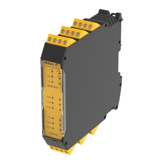
Page 44: Output Module 485Epa04
7.3.7 Output module 485EPA04 MEANING IN FAIL EXT FAIL OSSD1/4 CLEAR1/4 STATUS1/4 GREEN ORANGE RED/GREEN YELLOW YELLOW Switch on - input test Tab. 7-24 Output view MEANING IN FAIL EXT FAIL OSSD1/4 CLEAR1/4 STATUS1/4 GREEN ORANGE RED/GREEN YELLOW YELLOW When the module waits for the when output in anticipation of first communication from the... -
Page 45: Module 485Epr04S00B
7.3.8 Module 485EPR04S00B MEANING IN FAIL EXT FAIL SEL 0/1 RELAY1/4 CLEAR1/4 GREEN ORANGE GREEN YELLOW Switch on - input test Tab. 7-26 Output view MEANING IN FAIL EXT FAIL SEL0/1 RELAY1/4 CLEAR1/4 GREEN ORANGE GREEN YELLOW When the module waits for the first in anticipation of with NO contact communication from the MASTER... -
Page 46: Module 485Epr04S08B
7.3.9 Module 485EPR04S08B MEANING IN FAIL EXT FAIL SEL0/1 RELAY1/4 CLEAR1/4 STATUS1/8 GREEN ORANGE GREEN YELLOW YELLOW Switch on - input test Tab. 7-28 Output view MEANING IN FAIL EXT FAIL SEL0/1 RELAY1/4 CLEAR1/4 STATUS1/8 GREEN ORANGE GREEN YELLOW YELLOW When the module waits for the first in anticipation of with NO contact... -
Page 47: Modules 485Eps2N, 485Eps1, 485Eps2
7.3.10 Modules 485EPS2N, 485EPS1, 485EPS2 MEANING IN FAIL EXT FAIL ENC* PROX GREEN GREEN ORANGE YELLOW YELLOW YELLOW Switch on - input test Tab. 7-30 Output view MEANING IN FAIL EXT FAIL ENC* PROX GREEN GREEN ORANGE YELLOW YELLOW YELLOW When the module waits Axis in the normal for the first... -
Page 48: Relay Output Modules 485Epr02/485Epr04
7.3.11 Relay output modules 485EPR02/485EPR04 MEANING OSSD1 RED/GREEN Switch on - input test Tab. 7-32 485EPR02 output view MEANING OSSD1 RED/GREEN NORMAL OPERATION RED with output OFF - GREEN with output ON Tab. 7-33 485EPR02 dynamic view MEANING OSSD1 OSSD2 RED/GREEN RED/GREEN Switch on - input test... -
Page 49: Fault Diagnosis
Fault diagnosis 7.4.1 Basic module 485EPB MEANING IN FAIL EXT FAIL IN1-8 OSSD1/2 CLEAR1/2 STATUS1/2 REMEDY GREEN ORANGE YELLOW BLUE RED/GREEN YELLOW YELLOW Flashing 2 Internal malfunction or 3 times Replace the module Reload the project. 5 times 5 times 5 times 5 times... -
Page 50: I/O Module 485Epe08A02
5 times 5 times compatible with basic Compatibility error flashing flashing flashing flashing flashing module, send to elobau for updating of the FW 4 flashes Check connections 4 times (only the LED of OSSD1/2 Fault OSSD outputs Specifies the... -
Page 51: Input Module 485Epe08
5 times 5 times compatible with basic Compatibility error flashing flashing flashing flashing flashing module, send to elobau for updating of the FW Specifies the Restart the system Error communication with 5 times address of If the problem persists, ... -
Page 52: Input Module 485Epe12
OSSD1/2 CLEAR1/2 STATUS1/2 REMEDY GREEN ORANGE YELLOW RED/GREEN YELLOW YELLOW Flashing 2 Send the module to elobau Internal malfunction or 3 times for repair Firmware version is not 5 times 5 times 5 times 5 times 5 times... -
Page 53: Input Module 485Epe16
5 times 5 times compatible with basic Compatibility error flashing flashing flashing flashing flashing module, send to elobau for updating of the FW Specifies the Restart the system Error communication with 5 times address of If the problem persists, ... -
Page 54: Output Module 485Epa02/485Epa04
5 times 5 times compatible with basic module, Compatibility error flashing flashing flashing flashing send to elobau for updating of the FW 4 flashes Check connections OSSD1/2 4 times (only the LED of the Fault OSSD outputs If the problem persists, replace Specifies the ... -
Page 55: Module 485Epr04S00B
EXT FAIL SEL0/1 RELAY1/4 CLEAR1/4 REMEDY GREEN ORANGE GREEN YELLOW Flashing 2 Send the module to elobau for Internal malfunction or 3 times repair Firmware version is not compatible 5 times 5 times with 485EPB, send to elobau for... -
Page 56: Module 485Epr04S08B
REMEDY GREEN ORANGE GREEN YELLOW YELLOW Flashing 2 Internal malfunction or 3 times Send the module to elobau for repair Firmware version is not compatible 5 times 5 times 5 times 5 times Compatibility error with 485EPB, send to elobau for... -
Page 57: Modules 485Eps2N, 485Eps1, 485Eps2
EXT FAIL ENC* PROX REMEDY GREEN ORANGE YELLOW YELLOW YELLOW Flashing 2 Send the module to elobau for Internal malfunction or 3 times repair Firmware version is not 5 times compatible with 485EPB, send to Compatibility error flashing... -
Page 58: Configuration Software
CONFIGURATION SOFTWARE The "eloProg 350EPKS" configuration software can be used to configure a logic diagram of the con- nections between the eloProg and the connected safety components/modules. The eloProg will thus monitor and control the connected modules/components. The configuration software uses a graphical interface (user interface) to establish the connections between the various components. -
Page 59: Fundamentals
8.1.4 Fundamentals Once the configuration software has been correctly installed it creates an icon on the desk- top. => To launch the program: double-click on this icon. The opening screen shown below is displayed: Fig. 8-1 User interface Now you are ready to create your project. Type no.: 350HB002 Version: 1.3 Date: 13.04.2016... -
Page 60: Standard Toolbar
11 -> REDO (RESTORE PREVIOUS CANCELLATION) 12 -> PROJECT VALIDATION 13 -> CONNECT TO eloProg 14 -> SEND PROJECT TO eloProg 15 -> QUIT CONNECTION TO eloProg 16 -> LOAD AN EXISTING PROJECT (from basic module) 17 -> MONITOR I/O status in real time - graphical) 18 ->... -
Page 61: Textual Toolbar
8.1.6 Textual toolbar Optionally the textual toolbar is also available (drop down). Fig. 8-3 Textual toolbar 8.1.7 Create a new project Select the icon in the standard toolbar to start a new project. A dialog is displayed to allow => entry of the project data (see Fig. -
Page 62: Edit Configuration (Composition Of The Various Modules)
The user identification dialog appears (see Fig. 8-6 User authentication). To accomplish this operation it is not necessary to log out of eloProg. It is generally used when a new user creates a new project or uses a previously created one. Fig. 8-6 User authentication Type no.: 350HB002... -
Page 63: Toolbar Buttons - Operators - Configuration
8.1.10 Toolbar buttons - Operators - Configuration 4 large tool windows are displayed to the left and right of the main window (see Fig. 8-7 Toolbar but- tons - Operators - Configuration). Fig. 8-7 Toolbar buttons - Operators - Configuration 1 Object tool window This contains the various function blocks. -
Page 64: Creating The Diagram (Configuration)
8.1.11 Creating the diagram (configuration) Once you have selected your system composition, you are ready to configure the project. The logic diagram is created by means of DRAG & DROP. Select the object as required from the windows described previously (each individual object is de- ... -
Page 65: Example Of A Project
Warning The validation function only verifies the consistency of programming with respect to the characteristics of the eloProg system. It does not guarantee that the device has been pro- grammed to meet all the safety requirements for the application. Type no.: 350HB002 Version: 1.3... -
Page 66: Project Report
The actual PL of the entire application and the relative parameters must consider data for all the devices connected to the eloProg system within the scope of the application. This must only be performed by the user/installer. ... -
Page 67: Connect To Eloprog
8-14). Fig. 8-11 Password request Send configuration to eloProg To send the saved configuration from a PC to basic module 485EPB, use this icon on the => standard toolbar and wait for the execution. The basic module will save the project in its internal memory and (if present) in the 350EPS memory stick (password level 2). -
Page 68: Configuration Log
The log file can be visualized using this icon in the standard toolbar (password level 1). => Fig. 8-12 LOG file System structure The current structure of the eloProg system can be checked using this symbol => (password level 1). A table appears showing: –... -
Page 69: Disconnecting The System
Fig. 8-15 Function MONITOR) in real time showing: – the status of the inputs (if the connected component is assigned to 2 or more inputs on the eloProg, only the first input is highlighted as active); see example in Fig. 8-15 Function MONITOR;... -
Page 70: Monitor (Status Of I/O In Real Time - Graphical)
MONITOR (status of I/O in real time - graphical) To enable / disable the MONITOR function, use this icon (password level 1). => The color of the connection line changes to the diagnostics view in real time: RED = OFF GREEN = ON DASHED ORANGE = External fault (for example, sensor not properly activated) DASHED RED = Waiting for restart;... -
Page 71: Password Protection
Note The password entered as default must be modified to avoid manipulation (level 2 pass- word) or so that the configuration loaded on eloProg (level 1 password) is not visible. Level 1 password All operators using the 485EPB system must have a Level 1 PASSWORD. -
Page 72: Password Change
Click on this icon. => Caution: Previously, access must be available to level 2. Otherwise, establish a connection and enter password, see Sec. Connect to eloProg on page 8-10. A window appears (see Fig. 8-17 Password change) allowing selection of the password to be changed. -
Page 73: System Test
This is done by forcing a change of status for each safety device connected to the eloProg to check that the status of the outputs actually changes. -
Page 74: Function Blocks
Function blocks 8.2.1 OUTPUTS OSSD (semiconductor safety outputs) The OSSD semiconductor safety outputs require no main- tenance, as they make use of (safe) solid state semicon- ductor technology. Output1 and Output2 supply 24 VDC when In is HIGH, likewise 0 VDC when In is LOW. Note Each pair of OSSD outputs has a corresponding RESTORE FBK input. -
Page 75: Fieldbus Probe (Fieldbus Sensor)
Then the state will be represented by 2 bytes on the fieldbus. (For details, see the fieldbus manual on the CD-ROM eloProg) Warning The PROBE output is not a safety output. Type no.: 350HB002 Version: 1.3... -
Page 76: Relay
RELAY The output function block Relay is a relay output with NO contact(s). The / relay outputs are closed when the input In = 1 corresponding to HIGH, otherwise the contacts are open (LOW). Parameter Category: There are 3 different categories of relay outputs: Category 1 Outputs with a relay category 1. - Page 77 Manual reset: If checked, the restart inhibit is activated after each fall of the signal at the input. Oth- erwise, the activation of the output is directly the state of input In. Reset type: There are 2 types of reset: Manual and Monitored. When Manual is selected the system only verifies the signal's transition from 0 to 1.
-
Page 78: Inputs
= 250 ms Note In the case of activation of manual reset successive inputs on the eloProg module must be used. Example: If Input 1 and 2 is used on the function block for In1 and In2 then Input 3 must be used for the Reset. - Page 79 Test outputs: Enables selection of which outputs with test signals are transferred to the Out Test output terminal(s). Short circuits and shorts circuits between the lines can be detected by means of this additional test. In order to do so, test signals (Test1-Test4) must be configured. Test at start up: This causes the test at the start of the external component (emergency stop button) to be activated.
-
Page 80: E-Gate (Mobile Separating Guard, Two-Channel)
= 250 ms Note In the case of activation of manual reset successive inputs on the eloProg module must be used. Example: If Input 1 and 2 is used on the function block for In1 and In2 then Input 3 must be used for the Reset. - Page 81 Filter (ms): Enables filtering of signals coming from the external contacts. This filter is configurable between 3 and 250 ms and eliminates possible contact bounce. The duration of this filter influences the total response time of the module. Activation contemporaneity: If this is selected, the contemporaneity test from external component signals is activated.
-
Page 82: Single E-Gate (Mobile Separating Guard, One-Channel)
= 250 ms Note In the case of activation of manual reset successive inputs on the eloProg module must be used. Example: If Input 1 is used on the function block for In1 then Input 2 must be used for the Reset. -
Page 83: Lock Feedback (Lock Monitoring)
LOCK FEEDBACK (lock monitoring) The function block LOCK FEEDBACK checks the inputs In for the (locking) state of an electromechanical interlocking guard (GUARD LOCK) for mobile separating guards or pro- tective doors. In the case the inputs indicate that the lock is closed, the output Output is HIGH. -
Page 84: Enable (Key Switch)
1 and then back to 0 is verified. Note In the case of activation of manual reset successive inputs on the eloProg module must be used. Example: If Input 1 and 2 is used on the function block for In1 and In2 then Input 3 must be used for the Reset. - Page 85 Test outputs: Enables selection of which outputs with test signals are transferred to the Out Test output terminal(s). Short circuits and shorts circuits between the lines can be detected by means of this additional test. In order to do so, test signals (Test1-Test4) must be configured. Test at start up: If checked, this activates the test at the start-up of the external component.
-
Page 86: Espe (Electro Sensitive Protective System: Safety Light Barrier / Laser Scanner)
= 250 ms Note In the case of activation of manual reset successive inputs on the eloProg module must be used. Example: If Input 1 and 2 is used on the function block for In1 and In2 then Input 3 must be used for the Reset. -
Page 87: Footswitch (Safety Pedal / Foot Switch)
= 250 ms Note In the case of activation of manual reset successive inputs on the eloProg module must be used. Example: If Input 1 and 2 is used on the function block for In1 and In2 then Input 3 must be used for the Reset. - Page 88 Test at start up: If checked, this activates the test at the start-up of the external component. This test requires actuating and releasing the pedal, in order to perform a complete function test and en- able the output Output. This check is only required at start-up of the machine (when the module is switched on).
-
Page 89: Mod-Sel (Mode Selection Switch)
MOD-SEL (mode selection switch) The function block MOD-SEL checks the inputs In for the status of a mode selection switch (up to 4 inputs). If only one of the inputs is HIGH, the corresponding output is set to HIGH. In the remaining cases, that is, with all inputs LOW or more than one input to HIGH, all outputs are LOW. -
Page 90: Photocell (Safety Light Barrier)
= 250 ms Note In the case of activation of manual reset successive inputs on the eloProg module must be used. Example: If Input 1 is used on the function block for In then Input 2 must be used for the Reset. -
Page 91: Two-Hand (Two Hand Control)
TWO-HAND (two hand control) The function block TWO-HAND checks the inputs In for the status of a two-hand switch. If a simultaneous actuation (within max. 500 ms) is carried out by the two keys, the output Output is HIGH. This status lasts until the keys are released. -
Page 92: Sensor (Photocell, Initiator)
= 250 ms Note In the case of activation of manual reset successive inputs on the eloProg module must be used. Example: If the Input 1 used for In1 on the function block, the input 2 must be used for the Reset. -
Page 93: S-Mat (Safety Mat)
= 250 ms Note In the case of activation of manual reset successive inputs on the eloProg module must be used. Example: If Input 1 and 2 is used on the function block for In1 and In2 then Input 3 must be used for the Reset. -
Page 94: Switch
= 250 ms Note In the case of activation of manual reset successive inputs on the eloProg module must be used. Example: If the Input 1 used for In1 on the function block, the input 2 must be used for the Reset. -
Page 95: Enabling Grip Switch (Enabling Switch)
ENABLING GRIP SWITCH (enabling switch) The function block ENABLING GRIP SWITCH checks the in- puts In for the status of an enabling switch. If the enabling switch is not actuated (position 1) or is fully depressed (posi- tion 3), the output Output = 0 (LOW). If it is semi-depressed (position 2), the output Output = 1 (HIGH). - Page 96 POSITION 1: Enabling switch completely released POSITION 2: Enabling switch pressed to center position POSITION 3: Enabling switch completely depressed Switch position Input 1 Input 2 Output Tab. 8-1 Mode, input type "Dual NO" POSITION 1: Enabling switch completely released POSITION 2: Enabling switch pressed to center position POSITION 3: Enabling switch completely depressed Switch position...
-
Page 97: Testable Safety Device (Mechanical Safety Switch)
TESTABLE SAFETY DEVICE (mechanical safety switch) The function block TESTABLE SAFETY DEVICE checks the inputs In for the status of a one-channel or two-channel (mechanical) safety switch as NO or NC contact. Deter- mine the type of sensor based on these tables. (Single NC) (Single NO) INPT1... - Page 98 Note In the case of activation of manual reset successive inputs on the eloProg module must be used. Example: If Input 1 and 2 is used on the function block for In1 and In2 then Input 3 must be used for the Reset.
-
Page 99: Solid State Device (Safety Sensor With Semiconductor Outputs)
= 250 ms Note In the case of activation of manual reset successive inputs on the eloProg module must be used. Example: If Input 1 and 2 is used on the function block for In1 and In2 then Input 3 must be used for the Reset. -
Page 100: Fieldbus Input (Fieldbus Inputs)
They are represented on the field bus with one byte. (For more information, see instructions for fieldbuses on the eloProg CD-ROM.) Warning The FIELDBUS INPUT is NOT a safety input. LL0-LL1 These allow a predefined logical level to be entered on a component’s input. -
Page 101: Function Blocks Of Type Speed Monitoring
Function blocks of type SPEED MONITORING SPEED CONTROL The function block SPEED CONTROL compares the set speed with a connected sensor (encoder / initiator). The out- put Over is LOW when the measured speed exceeds a spec- ified limit (overspeed). If the measured speed is below this limit, the output is HIGH. - Page 102 Threshold number (number of speed limits): Possible selection: – 1 threshold (default) – 2 thresholds Input of 2 thresholds – 4 thresholds No. limits Enables you to define up to 4 different speed limits (thresh- Speed 1 olds), of which, however, only one can be active at a time. Speed 2 Selection of the active threshold is achieved via the inputs In1 Input of 4 thresholds...
- Page 103 If the displayed values appear RED, then the measurement parameters are outside the processing limits of the eloProg module. The parameters given in the following formulas must be adapted. 1. Frequency calculation for axis type Rotating, Rotating sensor f [Hz] = speed [RPM] x resolution [pulse/R] 2.
-
Page 104: Window Speed Control (Speed Control In Measuring Window)
WINDOW SPEED CONTROL (speed control in measuring window) The function block WINDOW SPEED CONTROL com- pares the set speed with a connected sensor (encoder / initiator) for a specified range. The output Window is LOW when the measured speed is outside the range (above / below) the specified area (Window). - Page 105 If the displayed values appear RED, then the measurement parameters are outside the processing limits of the eloProg module. The parameters given in the following formulas must be adapted. Type no.: 350HB002 Version: 1.3...
- Page 106 1. Frequency calculation for axis type Rotating, Rotating sensor f [Hz] = speed [RPM] x resolution [pulse/R] 2. Frequency calculation for axis type Linear, Rotating sensor f [Hz] = speed [m/min] x 1000 x resolution [pulse/R] 60 x pitch [mm/R] 3.
-
Page 107: Still Stand (Stillstand Check)
STILL STAND (stillstand check) The function block STAND STILL checks the speed of a con- nected sensor (encoder / initiator) to a halt, or to an upper speed limit. If the measured speed is below the specified limit in the speed field speed limit Null the output Zero is HIGH. If this value is exceeded, the output Zero is LOW. - Page 108 If the displayed values appear RED, then the measurement parameters are outside the processing limits of the eloProg module. The parameters given in the following formulas must be adapted. Type no.: 350HB002 Version: 1.3...
- Page 109 1. Frequency calculation for axis type Rotating, Rotating sensor f [Hz] = speed [RPM] x resolution [pulse/R] 2. Frequency calculation for axis type Linear, Rotating sensor f [Hz] = speed [m/min] x 1000 x resolution [pulse/R] 60 x pitch [mm/R] 3.
-
Page 110: Stand Still And Speed Control (Speed And Standstill Control)
STAND STILL AND SPEED CONTROL (speed and standstill control) The function block STAND STILL AND SPEED CONTROL compares 2 separately adjustable speed types (for station- ary and overspeed) with a connected sensor (encoder / initi- ator). Standstill control: If the measured speed is below the specified limit in the speed field speed limit zero the output Zero is HIGH. - Page 111 Direction selection: Sets the direction of rotation for the specified limit values (reference value). The possible choices are: – Bidirectional – Clockwise – Counter-clockwise If Bidirectional is selected, the threshold is detected whether the axis rotates clockwise or counter- clockwise. Selecting Clockwise or Counter-clockwise will cause it to be detected only when the axis rotates in the selected direction.
- Page 112 If the displayed values appear RED, then the measurement parameters are outside the processing limits of the eloProg module. The parameters given in the following formulas must be adapted. Type no.: 350HB002 Version: 1.3...
- Page 113 1. Frequency calculation for axis type Rotating, Rotating sensor f [Hz] = speed [RPM] x resolution [pulse/R] 2. Frequency calculation for axis type Linear, Rotating sensor f [Hz] = speed [m/min] x 1000 x resolution [pulse/R] 60 x pitch [mm/R] 3.
-
Page 114: Guard Lock Block
8.3.1 GUARD LOCK block GUARD LOCK: Safety guard lock The block GUARD LOCK checks the state of an elec- tromechanical locking system with guard (interlock) and checks the consistency and plausibility of the sig- nals of the safety circuit on mobile separating guards (e-gates), the monitoring circuit (Lock fbk) and the un- locking / locking requests (UnLock cmd). - Page 115 = 250 ms Note In the case of activation of manual reset successive inputs on the eloProg module must be used. Example: If inputs 1, 2 and 3 are used for Gate, Lock fbk and UnLock cmd, Input 4 must be used for Reset.
-
Page 116: Operators (Processing Blocks)
Operators (processing blocks) The signals of the inputs of each processing block can be inverted: (logically: NOT) by placing the cursor on the corresponding pin (e.g. In1) and pressing the right mouse key. A ring appears, indicat- ing the reversal of the signal. The next time the right mouse button is pressed, the signal will be re- versed and (the ring) deleted. -
Page 117: Not: Inverter Block
NOT: Inverter block Logic block NOT inverts the logical status of input In. Note The possibility of inverting inputs (read the instructions at the beginning of section) can partially reduce NOT gates in the configuration. OR: OR block Logic block OR results in output Output going HIGH, when at least one input In is HIGH. -
Page 118: Xor (Exclusive Or): Exclusive Or Block
XOR (EXCLUSIVE OR): Exclusive OR block Logic block XOR results in output Output going HIGH, when the number of inputs In are in state HIGH odd. In all other cases, the output is LOW. Result link All LOW HIGH, odd HIGH, odd HIGH, even HIGH, odd... -
Page 119: Multiplexer: Selection Switch
MULTIPLEXER: Selection switch The logic block MULTIPLEXER selects from 1 from max. 4 signal inputs In and routes the selected signal to output Output. To select the desired signal input In , the corresponding input selection input Sel is controlled with HIGH. In doing so, only 1 selection input may be controlled at the same time with HIGH. -
Page 120: Memory Blocks
8.4.2 Memory blocks Memory modules offer the opportunity to store signals (HIGH or LOW) (for example, from other com- ponents of the project) in order to be able to reprocess them as required. The state changes occur in accordance with the truth tables that are shown for each individual oper- ator. -
Page 121: User Restart Manual: Restart Inhibit, Reset With Rising Edge
USER RESTART MANUAL: Restart inhibit, reset with rising edge The USER RESTART MANUAL function block serves as restart inhibit. The output of the safety device is applied to the input In, the Start button is applied to the edge- triggered Restart input. Start (Q output HIGH) is done with a rising edge, according to the following truth table. -
Page 122: Counter Blocks
8.4.3 Counter blocks Counter modules generate a HIGH at output Q as soon as the preselected number of pulses (value in the Count field) is achieved. COUNTER: Counter, up and down The COUNTER block is a pulse counter. Counter type: There are 3 types of counters (modes): There are 3 modes: 1. - Page 123 2. The counting is realized (as described above) by adding the pulses to Ck up and subtracting to Ck down (if input Ck downis enabled). Once the preselected value (Count field) is reached, the output Q goes HIGH (static). With a HIGH level on input Clear, it is possible to change output Q back to LOW (if input Clear is activated).
-
Page 124: Timer Operators
8.4.4 TIMER operators The timer modules generate a signal (high or low) for a specified period. CLOCKING: Clock generator, controllable The CLOCKING block supplies output Out with a contin- uous clock signal with a set period length T, so long as input In is HIGH. -
Page 125: Monostable: Monoflop
MONOSTABLE: Monoflop Rising edge mode: Minimum time HIGH level The block MONOSTABLE supplies at output Out a HIGH, that corresponds to a minimum of the period set in field Time (10 ms to 1093 s). The HIGH is started with a rising edge (LOWHIGH) on input In. -
Page 126: Passing Make Contact: Maximum Time (Pulse Time Limiter)
PASSING MAKE CONTACT: Maximum time (pulse time limiter) Block PASSING MAKE CONTACT enables output Out to generate the same signal is present on input In (see figure). However, if this remains HIGH longer than specified time (value in the time field), the output Out changes to LOW. -
Page 127: Delay: On / Off Delay
DELAY: ON / OFF delay The block DELAY can be used to delay a HIGH level on input In (according to the set in the Time field) to the output Out. Parameter Time: The maximum period T can be set from 10 ms to 1093 s (confirm with Return key). - Page 128 Falling edge mode: Switch-off delay A rising edge at the input In immediately causes output Out to go HIGH. The delay begins with the falling edge of the signal at the input In. After the configured time T has elapsed, output Out changes to LOW, if input In is also LOW at this time, and remains as long as input In is LOW.
-
Page 129: Muting
The safe operation is monitored by a suitable muting block in the SAE (e.g. eloProg). The muting sensor signals (and possibly additional parameters) must be provided in the allowable form and sequence (depending on the muting module and the respective configuration) so that the muting process is initiated. - Page 130 With Muting Out (signal output): Output is HIGH during the muting sequence. Direction (material transport direction): Possible values: Up, Down, BIDIR For double parallel muting it is possible to initiate the muting process from both sides of the electro sensitive protective system. The allowable sequence of operation of the sensors can be defined with the Direction option.
-
Page 131: Muting "L" (L-Arrangement): 2 Sensor Single-Side Muting (Parallel)
MUTING "L" (L-arrangement): 2 Sensor single-side muting (parallel) Activation of the muting function is carried out following the simultaneous damping of the sensors S1 & S2. Muting ends immediately after the ESPE (safety light curtain) is clear. The allowed time offset between the sensor signals S1 & S2 and S3 & S4 can be between 2 and 5 seconds (optional sensor-time). -
Page 132: Muting "Seq" (Sequential): 4-Sensor Muting (Serial)
MUTING "Seq" (Sequential): 4-sensor muting (serial) Activation of the muting function is carried out following the serial damping of the sensors S1, S2, and then S3, S4. In the event of material flow in the opposite direction, the sequence takes place in reverse order. The function block MUTING "Seq"... - Page 133 Quit muting: Possible values: CURTAIN, SENSOR. This parameter defines at what point the muting operation is terminated. If you select CURTAIN the muting closes immediately when the ESPE is released (rising edge on Input of the Muting block), if you select SENSOR it closes when the penultimate has been cleared. Select CURTAIN Input Muting...
-
Page 134: Muting "T" (T-Arrangement): 2 Sensor Two-Sided Muting (Parallel)
MUTING "T" (T-arrangement): 2 Sensor two-sided muting (parallel) Activation of the muting function is carried out following the simultaneous damping of the sensors S1 & S2. The allowed time offset between the sensor signals S1 & S2 can be between 2 and 5 seconds (optional sensor-time). -
Page 135: Muting Override
MUTING OVERRIDE If a fault occurs during the muting operation, the override function can be used to remove any remaining cargo in the transit (muting range). The Output is held during the override opera- tion on HIGH. The input of the function block Input MUTING OVERRIDE is connected to the output Outputof a muting MUTING block "X", which then allows you to manually override the input Input (when Input is LOW) by a rising edge on input... - Page 136 With sensors occupied: When using Muting blocks "Con", "Seq" and "T", this option must be selected, for Muting block "L", the option may not be selected. Otherwise, a warning is displayed in the compilation phase and in the report. Timeout (override termination after expiration of time): Values from 10s...∞ The override cycle must be stopped within the selected time (slide control).
-
Page 137: Various Function Blocks
Various function blocks SERIAL OUTPUT: Serial transmission of status signals The function block SERIAL OUTPUT transmits the sta- tus of up to 8 inputs (In1…In8) on the output Output and converts them into a serial format. Function The serial-output function encodes and transmits the status of all connected inputs with 2 different methods to output Output: Asynchronous method of coding:... -
Page 138: Network
Function This feature allows for easy distribution of stop and restore commands on a local eloProg network. The following is always the case for the NETWORK function: 1. The Network_In input connected to a single or double input must be connected to the Network_Out output of the preceding unit in the local network. - Page 139 Note The maximum number of MASTER modules that can be connected in network configura- tion is 10. Condition 1: With reference to Fig. 8-22 Example of application network data flow on page 8-81 - if the following occurs on power-on: 1.
- Page 140 Example of a 4 node network: MASTER MASTER n°1 MASTER n°2 MASTER n°3 EMERGENCY STOP 120 ms x n° module 120 ms x n° module 120 ms x n° module 12.6 ms 120 ms 240 ms 360 ms Master 12.6 ms 360 ms Master Master...
-
Page 141: Interpage In/Out
The Reset_in and Network_in inputs and the Network_out output can only be mapped to the I/O pins of the MASTER. Fig. 8-24 Example of use of the NETWORK block INTERPAGE IN/OUT If the diagram is very complex, and a connection between two very widely separated objects is re- quired, use the "Interpage"... -
Page 142: Special Applications
8.5.1 Special applications Output delay with manual operation If you need to have 2 outputs, the second of which is delayed (in Manual mode) use the following scheme: Fig. 8-25 Two outputs with second one delayed in MANUAL mode Note When using the timer function DELAY (see Sec. -
Page 143: Eloprog Error Codes
8.5.2 EloProg error codes In the case of malfunctions is the eloProg system is able to transmit the error code to the eloProg software corresponding to the error detected by the master 485EPB. To read the code, proceed as follows: –... -
Page 144: Accessories And Spare Parts
DESCRIPTION 485EPB eloProg basic unit 8 inputs / 2 solid state outputs (pairs) 485EPE08A02 eloProg I/O expansion unit 8 inputs / 2 solid state outputs (pairs) 485EPE08 eloProg input expansion unit (8 x) 485EPE12 eloProg input expansion unit 12 x... -
Page 145: Eu-Declaration Of Conformity
EU-DECLARATION OF CONFORMITY elobau GmbH & Co. KG Zeppelinstraße 44 D-88299 Leutkirch +49-7561-970-0 / www.elobau.de EU-Konformitätserklärung EU- Declaration of Conformity Hiermit erklären wir, dass das nachfolgend aufgeführte Produkt aufgrund der Konzipierung und Bauart den Sicherheits- und Gesundheitsanforderungen der unten genannten EU-Richtlinien entspricht. - Page 146 GmbH & Co. KG Zeppelinstraße 44 D-88299 Leutkirch Internet: www.elobau.com Service-phone eloProg : 0049 (0) 7561/970110 Service-email eloProg : service@elobau.com Type no.: 350HB002 Version: 1.3 Date: 13.04.2016 10-2...
Need help?
Do you have a question about the eloProg and is the answer not in the manual?
Questions and answers