
Related Manuals for elobau eloProg


Summary of Contents for elobau eloProg
- Page 1 - Vers. 1.0 eloProg Configurable safety system Manual Product description Doc.-No. 350HB002en Last updated: 05/20111 (Vers. 1.0)
-
Page 2: Table Of Contents
(350EPS ) ......................13 MULTIPLE LOAD function ........................13 RESTORE function ..........................13 EXAMPLE OF CONNECTION OF eloProg TO THE MACHINE CONTROL SYSTEM ......18 CHECKLIST AFTER INSTALLATION ......................18 OPERATING DIAGRAM ..........................19 SIGNALS ................................20 INPUTS ............................... - Page 3 How to install the configuration software ....................41 Fundamentals ............................42 Standard tool bar ............................ 43 Create a new project (configure the eloProg system) ................44 EDIT CONFIGURATION (composition of the various modules) ............45 Change user parameters ........................45 OBJECTS - OPERATOR - CONFIGURATION tool bars ...............
- Page 4 - Vers. 1.0 TIMER OPERATORS (max number = 8) ....................73 CLOCKING ............................73 MONOSTABLE ........................... 74 PASSING MAKE CONTACT ......................75 DELAY ..............................76 MUTING OPERATORS (max number = 4) ..................... 77 "Concurrent" MUTING ........................77 MUTING “L” ............................78 "Sequential"...
-
Page 5: Introduction
This symbol indicates an important instruction. The eloProg is built to the following safety levels: SIL 3, SILCL 3, PL e, Cat. 4, Type 4 in accordance with the applicable standards. -
Page 6: Abbreviations And Symbols
- Vers. 1.0 Abbreviations and symbols 350EPS = eloProg memory stick: for basic module 485EPB (accessory) 350EPT = eloProg t-fitting 350EPKS = eloProg configuration software OSSD = Output Signal Switching Device: solid state safety output MTTF Mean Time to Dangerous Failure... -
Page 7: Overview
- Vers. 1.0 OVERVIEW eloProg is a modular safety controller. It consists of a master unit (485EPB), which can be configured using the configuration software graphic interface, and a number of expansion units connected via the proprietary bus. The master unit can also be used as a stand-alone device. It has 8 safety inputs and 2 independent programmable dual channel outputs. -
Page 8: Product Composition
- Vers. 1.0 PRODUCT COMPOSITION The basic module 485EPB is supplied with: • CD-ROM containing the free configuration software SW and PDF handbook. NB: the rear panel connector (t-fitting350EPT) and memory stick (350EPS) can be ordered separately as accessories. -
Page 9: Installation
- Vers. 1.0 INSTAL LLATIO Mechan nical fast ening Fix the mo odules to a a 35mm DI IN rail as fo ollows: 1. Co onnect the s same num mber of t-fitt tings as th e number of units to be installe 2. -
Page 10: Calculation Of Safety Distance Of An Espe Connected To Eloprog
Remember that the total response time depends on: eloProg response time + ESPE response time + response time of the machine (i.e. the time taken by the machine to stop the dangerous movement from the moment in which the stop signal is transmitted). -
Page 11: Instructions Concerning Connection Cables
- Vers. 1.0 Instructions concerning connection cables Cables used for connections must be AWG26 - AWG14. Cables used for connections of longer than 50m must have a cross-section of at least 1mm (AWG16). We recommend the use of separate power supplies for the safety module and for other electrical power equipment (electric motors, inverters, frequency converters) or other sources of disturbance. -
Page 12: Usb Input
- Vers. 1.0 USB input The basic module 485EPB includes a USB 2.0 connector for connection to a Personal Computer where the configuration software resides. USB-cable 350EPU (3m) available as an accessory. Figure 2 - USB 2.0 front panel connector... -
Page 13: Eloprog Memory Stick (350Eps )
- Vers. 1.0 oProg mem mory stick ( (350EPS ) backup me emory, calle ed 350EPS S (optional) n be install led in the b basic modu ule 485EPB d used to o save th he SW co onfiguration rameters. - Page 14 Each time memory stick is used, carefully check that the chosen configuration is the one that was planned for that particular system. Try again a fully functional test of the system composed of eloProg plus all devices connected to it (see the TESTING the system section).
- Page 15 - Vers. 1.0 485EPE08A02 TERMINAL SIGNAL TYPE DESCRIPTION OPERATION 24VDC 24VDC power supply NODE_SEL1 Input Input ("type B" according to EN 61131-2 ) Node selection NODE_SEL2 Input Input ("type B" according to EN 61131-2 ) 0VDC power supply OSSD1_A...
- Page 16 - Vers. 1.0 485EPE08 TERMINAL SIGNAL TYPE DESCRIPTION OPERATION 24VDC 24VDC power supply NODE_SEL1 Input Input ("type B" according to EN 61131-2 ) Node selection NODE_SEL2 Input Input ("type B" according to EN 61131-2 ) 0VDC power supply INPUT1...
- Page 17 - Vers. 1.0 485EPA02 TERMINAL SIGNAL TYPE DESCRIPTION OPERATION 24VDC 24VDC power supply NODE_SEL1 Input Input ("type B" according to EN 61131-2 ) Node selection NODE_SEL2 Input Input ("type B" according to EN 61131-2 ) 0VDC power supply OSSD1_A...
-
Page 18: Example Of Connection Of Eloprog To The Machine Control System
EXAMPLE OF CONNECTION OF eloProg TO THE MACHINE CONTROL SYSTEM Figure 4 CHECKLIST AFTER INSTALLATION The eloProg system is able to detect the faults that occur in each own module. Anyway to have the system perfect perform the following checks at start up and at least every one year: Operate a complete system TEST (see "TESTING the system") -
Page 19: Operating Diagram
- Vers. 1.0 OPERATING DIAGRAM Mechanical fastening Electrical connections between the eloProg modules and with the external sensors Designing the diagram Validation sw OK ? Connection via USB Downloading the diagram to master module Configuration control on master module OK? -
Page 20: Signals
The eloProg 485EPB master has two inputs: MASTER_ENABLE1 and MASTER_ENABLE2. These signals must both be permanently set to logic level 1 (24VDC) for the eloProg to operate. If the user needs to disable the eloProg simply lower these inputs to logic level 0 (0VDC). -
Page 21: Restart_Fbk
- Vers. 1.0 RESTART_FBK The RESTART_FBK signal input allows the eloProg to verify an EDM (External Device Monitoring) feedback signal from the external contactors, and to monitor Manual/Automatic operation (See the list of possible connections in Table 11). Each OSSD pairs has a RESTART_FBK corresponding input. -
Page 22: Outputs
- Vers. 1.0 OUTPUTS OUT STATUS The OUT STATUS signal is a programmable digital output that can indicate the status of: • An input. • An output. • A node of the logic diagram designed using the configuration software. -
Page 23: Safety Relays (485Epr02, 485Epr04)
- Vers. 1.0 SAFETY RELAYS (485EPR02, 485EPR04) Characteristics of the output circuit The 485EPR02/485EPR04 units use guided contact safety relays, each of which provides two N.O. contacts and one N.C contact in addition to the N.C. feedback contact. The 485EPR02 unit uses two safety relays and the 485EPR04 uses four. -
Page 24: Wiring Example 485Epr02 / 485Epb
- Vers. 1.0 Wiring example 485EPR02 / 485EPB Figure 7 Switching operation timing diagram Figure 8... -
Page 25: Technical Features
- Vers. 1.0 TECHNICAL FEATURES GENERAL SYSTEM CHARACTERISTICS Safety level parameters Parameter Value Standard ÷ 10 IEC 61508:1998 SILCL IEC 62061:2005 Type EN 61496-1 High ISO 13849-1:2006 MTTFd (years) 30 ÷ 100 IEC 62061:2005 Category Device lifetime 20 years... -
Page 26: Enclosure
- Vers. 1.0 Enclosure Electronic housing max 24 pole, Description with locking latch mounting Enclosure material Polyamide Enclosure protection class IP 20 Terminal blocks protection class IP 2X Fastening Quick coupling to rail according to EN 60715 Dimensions (h x l x d) 108 x 22.5 x 114.5... -
Page 27: 485Epe08 - 485Epe16 Modules
- Vers. 1.0 485EPE08 - 485EPE16 modules Model 485EPE08 485EPE16 24VDC ± 20% Rated voltage Dissipated power 3W max Digital INPUTS (No./description) PNP active high according to EN 61131-2 Test OUTPUT (No./description) 4 / to check for short-circuits-overloads Connection to 485EPB... -
Page 28: Mechanical Dimensions
- Vers. 1.0 MECHANICAL DIMENSIONS 99 mm 22.5 mm 108 mm Figure 9... -
Page 29: Signals
- Vers. 1.0 SIGNALS 485EPB IN FAIL EXT FAIL IN1÷8 OSDD1/2 CLEAR1/2 STATUS1/2 MEANING GREEN ORANGE BLUE YELLOW RED/GREEN YELLOW YELLOW Power on - initial TEST Memory stick 350EPS recognised (max (max 1s) Loading diagram from memory stick 350EPS... -
Page 30: 485Epe08A02
- Vers. 1.0 485EPE08A02 IN FAIL EXT FAIL IN1÷8 OSSD1/2 CLEAR1/2 STATUS1/2 MEANING GREEN ORANGE YELLOW RED/GREEN YELLOW YELLOW Power on - initial TEST Table 24 - Opening Screen IN FAIL EXT FAIL IN1÷8 OSSD1/2 CLEAR1/2 STATUS1/2 MEANING ORANGE... -
Page 31: 485Epe08
- Vers. 1.0 485EPE08 MEANING IN FAIL EXT FAIL IN1÷8 GREEN ORANGE YELLOW Power on - initial TEST Table 26 - Opening Screen MEANING IN FAIL EXT FAIL IN1÷8 GREEN ORANGE YELLOW if the unit is waiting for the first... -
Page 32: 485Epe16
- Vers. 1.0 485EPE16 MEANING IN FAIL EXT FAIL IN1÷16 GREEN ORANGE YELLOW Power on - initial TEST Table 28 - Opening Screen MEANING IN FAIL EXT FAIL IN1÷16 GREEN ORANGE YELLOW if the unit is waiting for the first... -
Page 33: 485Epa02
- Vers. 1.0 485EPA02 MEANING IN FAIL EXT FAIL OSDD1/2 CLEAR1/2 STATUS1/2 GREEN ORANGE RED/GREEN YELLOW YELLOW Power on - initial TEST Table 30 - Opening screen MEANING IN FAIL EXT FAIL OSSD1/2 CLEAR1/2 STATUS1/2 GREEN ORANGE RED/GREEN YELLOW... -
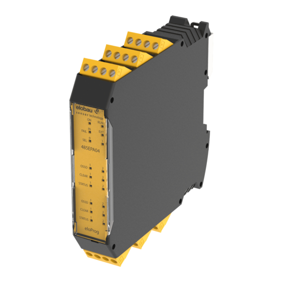
Page 34: 485Epa04
- Vers. 1.0 485EPA04 MEANING IN FAIL EXT FAIL OSDD1/4 CLEAR1/4 STATUS1/4 GREEN ORANGE RED/GREEN YELLOW YELLOW Power on - initial TEST Table 32 - Opening screen MEANING IN FAIL EXT FAIL OSDD1/4 CLEAR1/4 STATUS1/4 GREEN ORANGE RED/GREEN YELLOW... -
Page 35: 485Epr02 / 485Epr04
- Vers. 1.0 485EPR02 / 485EPR04 MEANING OSSD1 RED/GREEN Power on - initial TEST Table 34 - 485EPR02 - Opening screen OSSD1 MEANING RED/GREEN NORMAL OPERATION RED with output OFF - GREEN with output ON Table 35 - 485EPR02 - Dynamic screen... -
Page 36: Troubleshooting
- Vers. 1.0 TROUBLESHOOTING 485EPB MEANING IN FAIL EXT FAIL IN1÷8 OSSD1/2 CLEAR1/2 STATUS1/2 REMEDY GREEN ORANGE YELLOW BLUE RED/GREEN YELLOW YELLOW 2 or 3 Internal fault Replace the module flashes • Upload the project Configuration again. 5 flashes... -
Page 37: 485Epe08A02
- Vers. 1.0 485EPE08A02 IN FAIL EXT FAIL IN1÷8 OSSD1/2 CLEAR1/2 STATUS1/2 MEANING REMEDY GREEN ORANGE YELLOW RED/GREEN YELLOW YELLOW 2 or 3 Internal fault Replace the module flashes • Firmware version not compatible with Compatibility error 5 flashes... -
Page 38: 485Epe08
- Vers. 1.0 485EPE08 IN FAIL EXT FAIL IN1÷8 OSSD1/2 CLEAR1/2 STATUS1/2 MEANING REMEDY GREEN ORANGE YELLOW RED/GREEN YELLOW YELLOW 2 or 3 Internal fault Replace the module flashes • Firmware version not compatible with 485EPB, Compatibility error flashes... -
Page 39: 485Epe16
- Vers. 1.0 485EPE16 IN FAIL EXT FAIL IN1÷16 OSSD1/2 CLEAR1/2 STATUS1/2 MEANING REMEDY GREEN ORANGE YELLOW RED/GREEN YELLOW YELLOW 2 or 3 Internal fault Replace the module flashes • Firmware version not compatible with 485EPB, Compatibility error flashes... -
Page 40: 485Epa02 / 485Epa04
- Vers. 1.0 485EPA02 / 485EPA04 MEANING IN FAIL EXT FAIL OSSD1/4 CLEAR1/2 STATUS1/2 REMEDY GREEN ORANGE RED/GREEN YELLOW YELLOW 2 or 3 Internal fault Replace the module flashes • Firmware version not compatible with 485EPB, Compatibility error flashes... -
Page 41: Eloprog Safety Designer Software
- Vers. 1.0 eloProg safety designer SOFTWARE The "eloProg 350EPKS" application software can be used to configure a logic diagram of the connections between the eloProg (Master + expansions) and the components of the system being developed. The eloProg and its SLAVE units will thus monitor and control the connected safety components. -
Page 42: Fundamentals
- Vers. 1.0 Fundame ntals Once the configu ration softw ware has be een correctl y installed i it creates a n icon on th he desktop. To lau unch the pro ogram: doub ble-click on this icon. = =>... -
Page 43: Standard Tool Bar
- Vers. 1.0 Standard tool bar The standard tool bar is shown in Figure 24. The meanings of the icons are listed below: 1 -> CREATE A NEW PROJECT 2 -> CHANGE CONFIGURATION (composition of different modules) 3 ->... -
Page 44: Create A New Project (Configure The Eloprog System)
- Vers. 1.0 Create a new project (configure the eloProg system) Select icon CREATE from the standard tool bar (Figure 24) to start a new project. The user authentication window is displayed (Figure 25). Figure 25 Next the configuration software displays a window showing only the 485EPB. -
Page 45: Edit Configuration (Composition Of The Various Modules)
- Vers. 1.0 EDIT CON NFIGURAT TION (com mposition o of the vario us module The chang ge of the sy ystem com mposition is s obtained with the ic The config uration win dow is show wed again ( (Figure 26). -
Page 46: Objects - Operator - Configuration Tool Bars
- Vers. 1.0 OBJECTS - OPERATOR - CONFIGURATION tool bars Four large tool windows are displayed to the left and right of the main window (shown in ): Figure 28 1 > OBJECT TOOL WINDOW This contains the various function blocks that will make up your project; these... -
Page 47: Creating The Diagram (Figure 29)
- Vers. 1.0 Creating the diagram (Figure 29) Once you have selected your system composition, you are ready to configure the project. The logic diagram is created using a DRAG&DROP function: • Select the objects as required from the windows described previously (each single object is described in detail in the following sections) and drag it into the design area. -
Page 48: Example Of A Project
- Vers. 1.0 Example o of a projec Fehle r! Verweis squelle ko onnte nich ht gefunde en werden n. shows an n example o of a project in whic ch only the 485EPB un nit is connec... -
Page 49: Project Report
System co omposition w with proper rties of each h block. (Ico the standar rd toolbar). Connect t o eloProg After conne ecting 485E EPB to the P PC via USB B cable use the icon for the c connection. -
Page 50: Upload System Configuration
- Vers. 1.0 Upload sy ystem conf figuration The check of the actu al composit tion of the e eloProg sys stem is obta ained using the icon (Password d Required: level 1). A pop-up wind dow will ap... -
Page 51: Monitor (I/O Status In Real Time - Graphic)
- Vers. 1.0 MONITOR (I/O status in real time - graphic) To activate the monitor use the icon . (Password Required: level 1). The color of the connecting line changes in the diagnostic view in real time : RED = Off GREEN = On DASHED ORANGE = External failure (e.g. -
Page 52: Password Protection
Shou uld you forg get either of f these pass swords, plea ase contact t elobau sen nsor techno ology for an unloc cking passw word. This p password is s only given to the desi... -
Page 53: Testing The System
After validating and uploading the project to the 485EPB and connecting all the safety devices, you must test the system to verify its correct operation. This is done by forcing a change of status for each safety device connected to the eloProg to check that the status of the outputs actually changes. -
Page 54: Object Function Blocks
- Vers. 1.0 OBJECT FUNCTION BLOCKS OUTPUT OBJECTS OSSD (safety outputs) The OSSD semiconductor safety outputs require no maintenance, Output1 and Output2 supply 24Vdc if the input is 1 (TRUE), whereas they supply 0Vdc if the input is 0 (FALSE). -
Page 55: Input Objects
- Vers. 1.0 INPUT OBJECTS E-STOP (emergency stop) E-STOP function block verifies an emergency stop device inputs status. If the emergency stop button has been pressed the output is 0 (FALSE). If not the output is 1 (TRUE). Parameters Input type: - Single NC –... -
Page 56: E-Gate (Safety Gate Device)
- Vers. 1.0 Output test: This is used to select which test output signals are to be sent to the emergency stop pushbutton. This additional test makes it possible to detect and manage any short-circuits between the lines. There is a choice of 4 possible test output signals, Test Output 1 ÷ Test Output 4. - Page 57 - Vers. 1.0 WARNING: If the Enabled Reset is active, a consecutive Input has to be used. Example: Input 1 and Input 2 are used for the functional block, then Input 3 has to be used for the Reset Input.
-
Page 58: Enable (Enable Key)
- Vers. 1.0 ENABLE (enable key) ENABLE function block verifies a manual key device Input status. If the key is not turned the output is 0 (FALSE). Otherwise the output is 1 (TRUE). Parameters Input type - Single NO – Allows connection of components with two NO contacts - Double NO –... -
Page 59: Espe (Optoelectronic Safety Light Curtain / Laser Scanner)
- Vers. 1.0 Filter (ms): This is used to filter the signals coming from the external contacts. The filter can be configured to between 3 and 250 ms and eliminates any bouncing on the contacts. The length of the filter affects the calculation of the unit's total response time. -
Page 60: Footswitch (Safety Pedal)
- Vers. 1.0 Test at start-up: If selected this enables the test at start-up of the safety light curtain. This test is performed by occupying and clearing the area protected by the safety light curtain to run a complete function test and enable the output. This test is only requested at machine start-up (when the unit is switched on). - Page 61 - Vers. 1.0 WARNING: If the Enabled Reset is active, a consecutive Input has to be used. Example: Input 1 and Input 2 are used for the functional block, then Input 3 has to be used for the Reset Input.
-
Page 62: Mod-Sel (Safety Selector)
- Vers. 1.0 MOD-SEL (safety selector) The MOD-SEL function block verifies the status of the inputs from a mode selector (up to 4 inputs): If only one input is 1 (TRUE) the corresponding output is also 1 (TRUE). In all other cases, and thus when... - Page 63 - Vers. 1.0 WARNING: If the Enabled Reset is active, a consecutive Input has to be used. Example: Input 1 is used for the functional block, then Input 2 has to be used for the Reset Input. Output test: This is used to select which test output are to be sent to the photocell test input. This additional test makes it possible to detect and manage any short-circuits between the lines.
-
Page 64: Two-Hand Safety Control
- Vers. 1.0 TWO-HAND safety control The TWO HAND function block verifies the status of the inputs of a two hand control switch. Only if both press-buttons are pressed within 500 msec the output is 1 (TRUE). Otherwise the output is 0 (FALSE). -
Page 65: Sensor
- Vers. 1.0 SENSOR The SENSOR function block verifies the status of the input of a sensor (not a safety sensor). If the beam of the sensor is occupied (sensor output FALSE) the output is 0 (FALSE). Otherwise, with the beam clear and an output of 1 (TRUE) then the output is 1 (TRUE). -
Page 66: S-Mat (Safety Mat)
- Vers. 1.0 S-MAT (safety mat) The S-MAT function block verifies the status of the inputs of a safety mat. If a person stands on the mat the output is 0 (FALSE). Otherwise, with the mat clear, the output is 1 (TRUE). -
Page 67: Switch
- Vers. 1.0 Filter (ms): This is used to filter the signals coming from the external contacts. The filter can be configured to between 3 and 250 ms and eliminates any bouncing on the contacts. The length of the filter affects the calculation of the unit's total response time. -
Page 68: Comments
- Vers. 1.0 Filter (ms): This is used to filter the signals coming from the safety light curtain. The filter can be configured to between 3 and 250 ms and eliminates any bouncing on the contacts. The length of the filter affects the calculation of the unit's total response time. -
Page 69: Nand
- Vers. 1.0 NAND Logical NAND returns an output of 0 (FALSE) if all the inputs are 1 (TRUE). Parameters Number of inputs: this is used to set between 2 and 8 inputs. Logical NOT inverts the logical status of the input. -
Page 70: Nor
- Vers. 1.0 Logical NOR returns an output of 0 (FALSE) if at least one of the inputs is 1 (TRUE). Parameters Number of inputs: this is used to set between 2 and 8 inputs. Logical XOR returns an output 0 (FALSE) if the input's number at 1 (TRUE) is even or the inputs are all 0 (FALSE). -
Page 71: Multiplexer
- Vers. 1.0 MULTIPLEXER Logical MULTIPLEXER forwards the signal of the inputs to the output according to the Sel selection. If the SEL1÷SEL4 have only one bit set, the selected In n is connected to the Output. If the SEL... -
Page 72: Sr Flip Flop
- Vers. 1.0 SR FLIP FLOP SR FLIP FLOP operator brings output Q at 1 with Set, 0 with Reset. See the following truth table. SET RESET Keep memory USER RESTART MANUAL (max number = 8 with RESTART MONITORED) -
Page 73: Counter Operators
If this is not selected the operation is automatic. Once the set count is reached output Q is set to 1(TRUE) and stays in this condition for two internal eloProg cycles after which it is resetted. Ck down: Enables counting down. -
Page 74: Monostable
- Vers. 1.0 MONOSTABLE The MONOSTABILE operator generates a level 1 (TRUE) output activated by the rising edge of the input and remains in this condition for the set time. Parameters Time: The delay can be set to between 10 ms and 1093.3 s. -
Page 75: Passing Make Contact
- Vers. 1.0 PASSING MAKE CONTACT In the PASSING MAKE CONTACT operator the output follows the signal on the input. However if this is 1 (TRUE) for longer than the set time, the output changes to 0 (FALSE). < T <... -
Page 76: Delay
- Vers. 1.0 DELAY DELAY operator applies a delay to a signal by setting the output to 1 (TRUE) after the set time, against a change in the level of the input signal. Parameters Time: The delay can be set to between 10 ms and 1093.3 s... -
Page 77: Muting Operators (Max Number = 4)
- Vers. 1.0 MUTING OPERATORS (max number = 4) "Concurrent" MUTING The MUTING operator with "Concurrent" logic performs muting of the input signal through sensor inputs S1, S2, S3 and S4. Preliminary condition: The Muting cycle can only start if all the sensors are 0 (FALSE) and inputs are 1 (TRUE) (barrier free). -
Page 78: Muting "L
- Vers. 1.0 Blind Time: Only with Muting Close=Curtain, blind time is enabled if you know that after the complete transition of the pallet (muting cycle close) some protruding objects could still occupy the light curtain and send the input to 0 (FALSE). During blind time the input remains 1 (TRUE). Blind Time can range from 250 msecs to 1 second. -
Page 79: Sequential" Muting
- Vers. 1.0 "Sequential" MUTING The MUTING operator with "Sequential" logic performs muting of the input signal through sensor inputs S1, S2, S3 and S4. Preliminary condition: The Muting cycle can only start if all the sensors are 0 (FALSE) and the inputs are 1 (TRUE) (barrier free). -
Page 80: Muting "T
- Vers. 1.0 Blind Time: Only with Muting Close=Curtain, blind time is enabled if you know that after the complete transition of the pallet (muting cycle close) some protruding objects could still occupy the light curtain and send the input to 0 (FALSE). During blind time the input remains 1 (TRUE). Blind Time can range from 250 msecs to 1 second. -
Page 81: Special Applications
- Vers. 1.0 SPECIAL APPLICATIONS Output delay with manual If you need to have two OSSD outputs with one of them delayed (in MANUAL mode) use the following scheme: Figure 38 - Two outputs with one delayed (in MANUAL mode) -
Page 82: Accessories And Spare Parts
- Vers. 1.0 ACCESSORIES AND SPARE PARTS MODEL DESCRIPTION CODE 485EPB eloProg main unit (8 inputs / 2 double OSSD ) 485EPB 485EPE08A02 eloProg I/O expansion unit (8 inputs / 2 double OSSD) 485EPE08A02 485EPE08 eloProg input expansion unit (8 inputs) -
Page 83: Ec Declaration Of Conformity
- Vers. 1.0 EC DECLARATION OF CONFORMITY We declare that the system eloProg fulfil the conformity to the following guidelines: 2006/42/EC, 2004/108/EC Related harmonized standards: DIN EN ISO 13849-1, DIN EN 62061, DIN EN 61131-2, DIN EN 61496-1 Further realted standards:...
Need help?
Do you have a question about the eloProg and is the answer not in the manual?
Questions and answers