Table of Contents
Advertisement
Quick Links
Advertisement
Table of Contents

Related Manuals for Besantek BST-ET16


Summary of Contents for Besantek BST-ET16
- Page 1 BESANTEK GROUND TESTER BST-ET16 BST-ET17 BST-ET18 BST-ET19 !•� h•I ,o,111 ,..00000 llOOOO 0. 0 MANUAL Besantek Corporation Test Equipment Depot - 800.517.8431 - 99 Washington Street Melrose, MA 02176 TestEquipmentDepot.com...
-
Page 2: Table Of Contents
CONTENT I. Attention ..................1 II. Brief Introduction ................ 2 III. Specification ................3 1.Model ................. 3 2. Ranges and Accuracy of Measurement......3 3. Specifications ..............4 IV. Structure of Meter ..............5 V. Liquid Crystal Display ..............6 1. - Page 3 VII. Measurement Principle ............13 1. Principle of Resistance Measurement ......13 2. Principle of Current Measurement ........14 Ⅷ. Measurement Method of Earth Resistance ......14 1. Multi-Point Grounding System .......... 14 2. Limited Point Grounding System ........15 3.
-
Page 4: Attention
I. Attention Thank you for purchasing this ground tester from our company. In order to make better use of the product, please be certain: ----To read this user manual carefully. ----To comply with the operating cautions presented in this manual. Under any circumstances, use the Meter should pay special attention to safety. -
Page 5: Brief Introduction
II. Brief Introduction Its performance is mainly reflected in: Breakthrough in self-test the boot a long time to wait, start immediately into the test. Breakthrough relay self-test mode, using the most advanced processing algorithms and digital integration technology, a fully intelligent. ... -
Page 6: Specification
III. Specification 1.Model Range of Range of Storage Alarm Model specification measurement current function function √ 0.01Ω-1200Ω BST-ET16 65mm×32mm 0.0mA-20.0A 99 Units √ φ32mm 0.01Ω-1200Ω BST-ET17 0.0mA-20.0A 99 Units √ 0.01Ω-1200Ω BST-ET18 65mm×32mm 0.0mA-30.0A 99 Units √ φ32mm 0.01Ω-1200Ω BST-ET19 0.0mA-30.0A... -
Page 7: Specifications
3. Specifications IEC/EN61010-1, IEC/EN6010-2-032 Instrument safety: double insulation Insulation: class II Pollution degree: CAT I11150V to ground, Max 20A Overvoltage category: Degrees of protection: -IP30, Group Ill equipment as per EN 60529 Ed 92 -IK04, as per EN 50102 Ed 95 Dimensions(LxWxH): -Long jaw: 285mmx90mmx66mm;... -
Page 8: Structure Of Meter
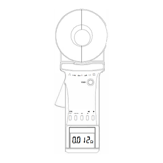
IV. Structure of Meter 1. Long Pincers Jaw : 65mmx32mm 2. Round Pincer Jaw : φ32mm 3. Trigger: to control opening and closing of jaw 4. HOLD Key: lock / Release display / Storage 5. ON/OFF Key: Boot Up / Shutdown /Quit /Clear Data 6. -
Page 18: Limited Point Grounding System
than its IEC parallel output value). But because a tower-grounding hemisphere was much smaller than the distance between the towers, and with a great number of locations after all, R is much smaller than R . Therefore, it can be justified to assume R =0 from an engineering perspective. -
Page 19: Single-Point Grounding System
It is nonlinear equations with N unknown numbers and N equations. It indeed has a definite solution, but it is very difficult to solve the issue artificially, even impossible when N is larger. Therefore, you’re expected to buy the Limited-Point Grounding System Solution software produced by this Company. - Page 20 As the resistance value measured by the Meter is the value of the series resistance from the testing line and two grounding resistances. Where: R is the resistance value measured with the Meter. is the resistance value of the testing line. Meter can measure out the resistance value by connecting the test lines with both ends.
-
Page 21: Ⅸ. Bill Of Loading
In the above three steps, the reading measured in each step is the value of the two series grounding resistance. In this way, we can easily calculate the value of each grounding resistance: From: R1=RA+RB R2=RB+RC R3=RC+RA We get: RA=(R1+R3-R2)÷2 This is the grounding resistance value of the grounding body R To facilitate the memory of the above formula, these three grounding bodies scan be viewed as a triangle;... -
Page 22: Ⅹ. Parts List And Assembly Details
Ⅹ. Parts List and Assembly Details 1. Parts List NAME Part Quantity/PCS Remark Screws battery DS01 M3X8 cover AA alkaline batteries DS02 Battery cover DS03 Upper shell DS04 Subjacent shell DS 05 Tension spring DS 06 Clamp DS 07 DS 08 HOLD key DS09 LCD cover... -
Page 24: Ⅺ.trouble Shooting
Ⅺ.Trouble shooting Symptoms Possible Causes Remedies No batteries. Set the batteries. Install batteries correct Faulty battery polarity polarity. Insufficient capacity of Replace the batteries. battery Poor contact of battery Replace the battery contacts. contacts Wrong battery type Replace with right type. instrument Make a continuity test of test A break in a battery... - Page 25 polluted by dust, oil etc. Re-boot follow the manual, Without self-calibration conduct measurement after before test self-calibration finished. Check above points first. If Defect circuit there is no problem, replace the component PCB, and do re-adjustment. Poor contact of LCD Re-plug the LCD connect plug connection wire or replace the plug.
- Page 27 Test Equipment Depot - 800.517.8431 - 99 Washington Street Melrose, MA 02176 TestEquipmentDepot.com...
Need help?
Do you have a question about the BST-ET16 and is the answer not in the manual?
Questions and answers