Yamaha TSX-10 Service Manual
Tabletop stereo system
Hide thumbs
Also See for TSX-10:
- Service manual (47 pages) ,
- Owner's manual (32 pages) ,
- Owner's manual (28 pages)
Table of Contents
Advertisement
Quick Links
TSX-10/15/20
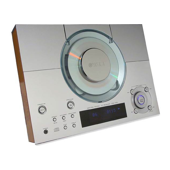
The TSX-10 is composed of the CRX-TS10 (cherry color) and the NX-TS10 (cherry color).
The TSX-15 is composed of the CRX-TS20 (black color) and the NX-TS10 (black color).
The TSX-20 is composed of the CRX-TS20 (black color) and the NX-TS20 (black color).
This manual has been provided for the use of authorized YAMAHA Retailers and their service personnel.
It has been assumed that basic service procedures inherent to the industry, and more specifically YAMAHA Products, are already
known and understood by the users, and have therefore not been restated.
WARNING:
IMPORTANT:
The data provided is believed to be accurate and applicable to the unit(s) indicated on the cover. The research, engineering, and
service departments of YAMAHA are continually striving to improve YAMAHA products. Modifications are, therefore, inevitable
and specifications are subject to change without notice or obligation to retrofit. Should any discrepancy appear to exist, please
contact the distributor's Service Division.
WARNING:
IMPORTANT:
CONTENTS
TO SERVICE PERSONNEL ...................................... 1~3
TOP PANELS ............................................................. 3~4
REAR PANEL ................................................................ 4
SPECIFICATIONS ...................................................... 5~6
INTERNAL VIEW ........................................................... 7
DISASSEMBLY PROCEDURES ................................... 8
SERVICING POSITION .................................................. 9
TEST MODE ........................................................... 10~11
CD TEST MODE ........................................................... 12
1 0 0 7 7 6
TABLETOP STEREO SYSTEM
IMPORTANT NOTICE
Failure to follow appropriate service and safety procedures when servicing this product may result in personal
injury, destruction of expensive components, and failure of the product to perform as specified. For these reasons,
we advise all YAMAHA product owners that any service required should be performed by an authorized
YAMAHA Retailer or the appointed service representative.
The presentation or sale of this manual to any individual or firm does not constitute authorization, certification or
recognition of any applicable technical capabilities, or establish a principle-agent relationship of any form.
Static discharges can destroy expensive components. Discharge any static electricity your body may have
accumulated by grounding yourself to the ground buss in the unit (heavy gauge black wires connect to this buss).
Turn the unit OFF during disassembly and part replacement. Recheck all work before you apply power to the unit.
SERVICE MANUAL
CD ERROR MESSAGE ......................................... 13~14
CD STANDARD OPERATION CHART ................. 15~17
IC DATA ................................................................. 18~23
DISPLAY DATA ........................................................... 24
BLOCK DIAGRAM ................................................. 25~27
PRINTED CIRCUIT BOARD .................................. 28~39
SCHEMATIC DIAGRAM ........................................ 40~42
PARTS LIST ........................................................... 43~53
REMOTE CONTROL TRANSMITTER ........................ 54
P.O.Box 1, Hamamatsu, Japan
Advertisement
Table of Contents

Related Manuals for Yamaha TSX-10


Summary of Contents for Yamaha TSX-10
-
Page 1: Table Of Contents
This manual has been provided for the use of authorized YAMAHA Retailers and their service personnel. It has been assumed that basic service procedures inherent to the industry, and more specifically YAMAHA Products, are already known and understood by the users, and have therefore not been restated. -
Page 2: To Service Personnel
TSX-10/15/20 AC LEAKAGE TO SERVICE PERSONNEL WALL EQUIPMENT TESTER OR OUTLET UNDER TEST EQUIVALENT 1. Critical Components Information Components having special characteristics are marked s a n d m u s t b e r e p l a c e d w i t h p a r t s h a v i n g specifications equal to those originally installed. - Page 3 TSX-10/15/20 PROTECTION OF EYES FROM LASER BEAM DURING SERVICING This set employs a laser. Therefore, be sure to carefully follow the instructions below when servicing. 1. Laser Diode Properties Optical Pick-up • Material : GaAlAs • Wavelength : 780 nm •...
-
Page 4: Top Panels
TSX-10/15/20 Grounding for electrostatic breakdown prevention 1. Human body grounding Use the antistatic wrist strap to discharge the static electricity from your body. 2. Work table grounding Anti-static wrist strip Put a conductive material (sheet) or steel sheet on the area 1MΩ... -
Page 5: Rear Panel
TSX-10/15/20 CRX-TS20: U, C, A, T models PRESET/TUNING STANDBY/ON OPEN/CLOSE HOUR – HOUR NATURAL SOUND CD RECEIVER CRX-TS20 MEMORY AUTO/MAN'L PRESET/BAND INPUT SNOOZE TIME ADJ TIMER PHONES SLEEP DISPLAY MIN – A/B/C/D/E CRX-TS20: B, G models PRESET/TUNING STANDBY/ON OPEN/CLOSE HOUR –... -
Page 6: Specifications
TSX-10/15/20 SPECIFICATIONS Audio Section General Output Power Per Channel Power Supply (1 kHz, 10% THD, 4 ohms) U, C models ........AC 120 V, 60 Hz SP OUT L/R ..........18W + 18W A model ..........AC 240 V, 50 Hz (B, G models: DIN standard output power per channel) B, G models ........ - Page 7 TSX-10/15/20 • DIMENSIONS CRX-TS10/20 297mm ( 11-11/16" ) NX-TS10 NX-TS20 140mm ( 5-1/2" ) 77.5mm ( 3" ) 126mm ( 5" ) 146mm ( 5-3/4" )
-
Page 8: Internal View
TSX-10/15/20 INTERNAL VIEW 1 Pick-up Unit 7 Tuner Pack Unit 2 CD Lid Opening Motor Mount 8 MAIN (1) P.C.B. 3 DIGITAL (5) P.C.B. 9 Power Amplifier IC (IC5) 4 DIGITAL (1) P.C.B. 0 Power Transformer 5 DIGITAL (2) P.C.B. -
Page 9: Disassembly Procedures
TSX-10/15/20 DISASSEMBLY PROCEDURES (Remove parts in the order as numbered.) Disconnect the power plug from the AC outlet. 1. Separation of Top section and Bottom section a. Remove 4 screws (1) to remove the side panels. (Fig. Lower side b. Remove 7 screws (2). -
Page 10: Servicing Position
TSX-10/15/20 SERVICING POSITION When performing inspections, use the positions as shown in the figure. Be sure to pay attention to the following items when performing inspections. 1. Static electricity 2. Polarity of connectors 3. Laser light from the pickup Be sure to load a CD before turning on the power and take it out after turning off the power. Never turn on the power without a CD loaded . -
Page 11: Test Mode
TSX-10/15/20 TEST MODE POWER Off condition STANDBY/ON Key is pressed while pressing INPUT Key and PRESET/TUNING Key. TEST MODE indication. When present mode is TEST MODE UP TEST MODE DOWN carried out. PRESET/TUNING PRESET/TUNING PRESET/BAND Key Test mode number Test mode number Execute test mode. - Page 12 TSX-10/15/20 DISPLAY FUNCTION PRESET/BAND Key 06 Ver-A1.06 It is changed to the date indication. Version information of the microcomputer software. (*2) 06 '01.07.11 The date of the microcomputer software. It is changed to version indication. 07 SUM[f370] The calculation of SUM is done and Re-calculation.
-
Page 13: Cd Test Mode
TSX-10/15/20 CD TEST MODE Press the ”STANDBY/ON” key while pressing the ”STOP” key and the ”INPUT” key simultaneously, and the TEST MODE will be activated. On the FL display, an opening message appears for a few seconds. After a few... -
Page 14: Cd Error Message
TSX-10/15/20 CD ERROR MESSAGE (1) If a CD error occurs, an error message can be displayed by selecting “ CD TEST MODE 28 Error Msg” and pressing the “OPEN/CLOSE” key. (2) Shown below is an example of display. (“E-73” as an example) (3) Listed in the table below are error messages. - Page 15 TSX-10/15/20 c) Operates as if no disc loaded. (although loaded) 2) Troubleshooting from System Malfunctions a) CD lid fails to open/close. Does CD lid Poor CD lid operation close properly? Poor mechanism CD lid starts to operation move but stops.
-
Page 16: Cd Standard Operation Chart
TSX-10/15/20 CD STANDARD OPERATION CHART Turn ON the power. Select CD with the INPUT key. "No Disc" on display when no disc exists. Forced feed return. TRV signal output until the limit switch detects the end. Press the OPEN/CLOSE key. - Page 17 TSX-10/15/20 Spindle motor accelerated. Tracking servo turned ON. /TLOCK (IC406, 12 pin) = High to Low Spindle servo turned ON. VCO locked. Feed servo turned ON. Tracking gain roughly adjusted (automatic). Tracking balance adjusted (automatic). Focus balance adjusted (automatic). Focus gain precisely adjusted (automatic).
- Page 18 TSX-10/15/20 Playing Press the SKIP key. Muting turned ON. MUTE (IC201, 95 pin) = High to Low Track searched. Muting cancelled after finding the starting point. MUTE (IC201, 95 pin) = High to Low ~ Playing ~ "0:00" displayed. Press the STOP key.
-
Page 19: Ic Data
TSX-10/15/20 IC DATA IC406 : MN35511AL Signal Processor & Controller 58 59 56 19 49 8 7 9 44 46 45 47 48 52 53 67 62 15 14 68 73 72 74 75 13 55 78 80 79 SUBCODE TIMING DSL •... - Page 20 TSX-10/15/20 IC406 : MN35511AL Pin Description Pin No. Name Function BCLK Bit clock output for SR DATA (NC) LRCK L/R identification signal output (NC) SRDATA Serial data output (NC) DVDD1 Power supply for digital circuit (+5) DVSS1 GND for digital circuit...
- Page 21 TSX-10/15/20 IC406 : MN35511AL Pin Description Pin No. Name Function DSLF Loop filter terminal for DSL PLLF Loop filter terminal for PLL VCOF Loop filter terminal for VCO (+5) AVDD2 Power supply for analog circuit (for AD of DSL, PLL, DA output blocks)
- Page 22 TSX-10/15/20 IC201 : M30217MA-A209FP (Mask Rom) 16 bit µ-COM M30218FCFP (Flash Rom) SEGMENT28 DIGIT2 SEGMENT29 DIGIT3 SEGMENT30 DIGIT4 SEGMENT31 DIGIT5 SEGMENT32 DIGIT6 SEGMENT33 DIGIT7 SEGMENT34 DIGIT8 SEGMENT35 DIGIT9 DIGIT10 VPROTEC DIGIT11 A/D IN DIGIT12 /CMDSEL DIGIT13 LDR CTR STAT CLOSE...
- Page 23 TSX-10/15/20 IC201 : M30217MA-A209FP (Mask Rom) 16 bit µ-COM M30218FCFP (Flash Rom) FLD47 DIGIT 13 (13G) [VEE external pull-down required] FLD46 DIGIT 12 (12G) [VEE external pull-down required] FLD45 DIGIT 11 (11G) [VEE external pull-down required] FLD44 DIGIT 10 (10G)
- Page 24 TSX-10/15/20 IC201 : M30217MA-A209FP (Mask Rom) 16 bit µ-COM M30218FCFP (Flash Rom) • Extention OUT port (IC202: BU2092 / F) Pin No. Name Function 5(5) Tuner MUTE OUT (TUNER) [1: MUTE ON] 6(6) AMP MUTE OUT [0: MUTE ON] 7(7)
-
Page 25: Display Data
TSX-10/15/20 DISPLAY DATA BLOCK DIAGRAM V201 : 13-BT-191GN (V7357700) PATTERN AREA PIN CONNECTION Pin No. Connection Pin No. Connection Note : 1) F1, F2 ..Filament 2) NP ..No pin 3) IC ..Internal connection (IC pin should be electrically open on the PC board) 4) Pin No. - Page 26 TSX-10/15/20...
-
Page 27: Printed Circuit Board
TSX-10/15/20 PRINTED CIRCUIT BOARD (Foil side) CD DIGITAL OUT DIGITAL (1) P. C. B. (Lead Type Device) OPTICAL • Semiconductor Location Ref. No. Location From DIGITAL (5) IC405 To MAIN (1) To CD MECHANISM SPDL - SPDL + FLSW FEED -... - Page 28 TSX-10/15/20 PRINTED CIRCUIT BOARD (Foil side) DIGITAL (1) P. C. B. (Surface Mount Device) • Semiconductor Location Ref. No. Location D400 D401 D402 D403 D404 D405 D406 IC400 IC401 IC402 IC403 IC404 IC406 IC407 IC408 Q400 Q401 Q402 Q403 Q405...
- Page 29 TSX-10/15/20 PRINTED CIRCUIT BOARD (Foil side) DIGITAL (3) P. C. B. DIGITAL (4) P. C. B. DIGITAL (6) P. C. B. (Lead Type Device) (Lead Type Device) (Lead Type Device) To DIGITAL (1) From DIGITAL (1) From CD MECHANISM DIGITAL (5) P. C. B.
- Page 30 TSX-10/15/20 PRINTED CIRCUIT BOARD (Foil side) DIGITAL (3) P. C. B. DIGITAL (4) P. C. B. DIGITAL (6) P. C. B. (Surface Mount Device) (Surface Mount Device) (Surface Mount Device) • Semiconductor Location Ref. No. Location D201 D202 D203 D204...
- Page 31 TSX-10/15/20 • Semiconductor Location SPEAKERS SETTING SUBWOOFER PRINTED CIRCUIT BOARD (Foil side) – – Ref. No. Location HRIZ OTHER MAIN (1) P. C. B. (Lead Type Device) TUNER PACK UNIT From DIGITAL (1) To DIGITAL (2) MAIN (2) P. C. B.
- Page 32 TSX-10/15/20 • Semiconductor Location PRINTED CIRCUIT BOARD (Foil side) Ref. No. Location MAIN (1) P. C. B. (Surface Mount Device)
-
Page 33: Schematic Diagram
TSX-10/15/20 SCHEMATIC DIAGRAM (CD) DIGIAL 4 DIGIAL 1 ELECTRICAL VOLUME WITH INPUT SELECTOR DRIVE HEAD -11.3 DSP-DAC -11.3 CD MECHANISM MUTE -11.4 COMPARATOR Point A Pin 59 of IC406 TUNER IC401, 402: NJM2068MD IC408: NJM2903M Dual OP-Amp –IN – –... - Page 34 TSX-10/15/20 SCHEMATIC DIAGRAM (DIGITAL) FL DISPLAY 2SD1938F 2SC4488 MA8051-M DIGIAL 2 DTC144EKA RB501V-40 2SA1037K 1SS355 Anode 2SC2412K MA8068-M 2SB1132 MA8062-M DTA114EKA DTC143XKA DTC114EKA Cathode M30218FCFP BU2092 POWER SUPPLY -22.4 -27.5 To MAIN (1) 12.8 TC74HC4051AF S-29390AFJA AN4801SB-E1 NJM2068MD NJM2903M 12.8 12.8...
- Page 35 TSX-10/15/20 SCHEMATIC DIAGRAM (MAIN) SW MUTE IC6: BA15218F IC5: TA2020-020 MAIN 1 Dual OP-Amp. 20W x 2ch Digital Audio Amp. VDD1 HEADPHONE AMP & OUTP1 SUBWOOFER AMP 11.0 11.9 PROCESSING PGND1 & 14.0 14.0 14.0 14.0 MODULATION VDD1 AMP MUTE 11.0...
-
Page 36: Parts List
TSX-10/15/20 WARNING PARTS LIST Components having special characteristics are marked s and must be replaced with parts having specifications equal to those originally in- stalled. ELECTRICAL PARTS Carbon resistors (1/6W or 1/4W) are not included in the ELECTRICAL PARTS List. For the parts No. of the carbon resistors, refer to last page. - Page 37 TSX-10/15/20 P.C.B. DIGITAL Schm Schm Ref. PART NO. Description Markets Ref. PART NO. Description Markets V8000100 P.C.B. DIGITAL UCTABG C409 US035100 C.CE.M.CHP 0.1uF CB201 V7833200 CN.BS.PIN 20P SE C410 US061560 C.CE.CHP 56pF CB202 VQ044400 CN.BS.PIN C411 UA655470 C.MYLAR 0.47uF CB205 V7833100 CN.BS.PIN...
- Page 38 TSX-10/15/20 P.C.B. DIGITAL Schm Schm Ref. PART NO. Description Markets Ref. PART NO. Description Markets C473 UA653270 C.MYLAR 2700pF D207 VT332900 DIODE 1SS355 C474 UA653270 C.MYLAR 2700pF D208 VT332900 DIODE 1SS355 C475 UR866100 C.EL D209 V7446300 E1L31-3B0A2 C476 UR866100 C.EL...
- Page 39 TSX-10/15/20 P.C.B. DIGITAL & P.C.B. MAIN Schm Schm Ref. PART NO. Description Markets Ref. PART NO. Description Markets Q203 VV655700 TR.DGT DTC144EKA VP206500 HOLDER.FUS EYF-52BCT Q204 VP872700 2SC4488 S,T VP206500 HOLDER.FUS EYF-52BCT Q205 VV556500 2SA1037K Q,R,S CB10 VP206500 HOLDER.FUS EYF-52BCT...
- Page 40 TSX-10/15/20 P.C.B. MAIN Schm Schm Ref. PART NO. Description Markets Ref. PART NO. Description Markets UR866470 C.EL 4.7uF VS597600 DIODE.CHP RB160L-40 TE25 UR847100 C.EL 10uF VS597600 DIODE.CHP RB160L-40 TE25 UA655470 C.MYLAR 0.47uF VS597600 DIODE.CHP RB160L-40 TE25 UA655470 C.MYLAR 0.47uF VS597600 DIODE.CHP...
- Page 41 TSX-10/15/20 P.C.B. MAIN & Chip Resistors Schm Schm Ref. PART NO. Description Markets Ref. PART NO. Description Markets VV556400 2SC2412K Q,R,S RD350000 R.CAR.CHP 0Ω 1/10W VV556400 2SC2412K Q,R,S RD353100 R.CAR.CHP 1Ω 1/10W VC218900 2SC3330 R,S,T RD354100 R.CAR.CHP 10Ω 1/10W VZ725900...
- Page 42 TSX-10/15/20 EXPLODED VIEW (CRX-TS10/CRX-TS20) 1-1-6 1-1-4 1-22 1-1-3 1-52 1-48 1-41 1-21 1-53 1-46 1-37 1-48 1-35 1-1-5 1-1-12 1-32 1-1-11 1-52 1-57 1-45 1-47 1-70 1-56 1-42 1-56 1-43 1-36 1-31 1-4 (2) 1-44 1-34 1-13 1-55 1-33 1-51...
- Page 43 TSX-10/15/20 MECHANICAL PARTS Ref. PART NO. Description Remarks Markets 1-1-3 V7739000 WINDOW/CD GLASS CRXTS10 1-1-3 V7739100 WINDOW/CD GRAY CRXTS20 1-1-4 V7739200 COVER/PU 1-1-5 V7739300 COVER/PU-B 1-1-6 V7722600 HINGE/WINDOW 1-1-11 VT958800 FLAT HEAD P-TITE SCREW MFZN2BL 1-1-12 V8128400 FLAT HEAD P-TITE SCREW 2.3x5...
- Page 44 TSX-10/15/20 Ref. PART NO. Description Remarks Markets 1-57 VG893800 BIND HEAD P-TITE SCREW MFZN2BL 1-70 VQ472900 GREASE FLOIL G-31KB KANTO CHEMICAL V8000200 P.C.B. ASS'Y MAIN V8000300 P.C.B. ASS'Y MAIN V8000400 P.C.B. ASS'Y MAIN V8000500 P.C.B. ASS'Y MAIN V7424300 AM/FM TUNER...
- Page 45 TSX-10/15/20 Ref. PART NO. Description Remarks Markets V7738300 MOUNTING BRACKET V7741600 NON SKID PAD 4pcs/set V2728500 BIND HEAD S-TITE SCREW MFZN2BL LITHIUM BATTERY 3V CR2025/1FE New Parts NX-TS10 Ref. PART NO. Description Remarks Markets AAX30620 SATELLITE SPEAKER UNIT NX-TS10BL NX TS10A B...
- Page 46 TSX-10/15/20 EXPLODED VIEW (NX-TS10/NX-TS20) NX-TS10 101 x 1 102 x 1 14-1 NX-TS20 14-2 14-3 14-4 103 x 1 10-1...
-
Page 47: Remote Control Transmitter
TSX-10/15/20 REMOTE CONTROL TRANSMITTER Not mount = B, G models only 1Ω SID1003BQ 27Ω 2SC3265-0 CARR M34282M1-558GP-T4 XOUT mount 3.0V 0.1µF 4.00MHz U, C, A, T models B, G models KEY No. KEY FUNCTION CUSTOM DATA SLEEP STANDBY/ON B.BOOST ON/OFF BASS/TREBLE BASS/TREBLE LEVEL–...
Need help?
Do you have a question about the TSX-10 and is the answer not in the manual?
Questions and answers