Advertisement
Quick Links
WIRING DIAGRAMS (continued)
2 or More Sensors to System
Single Sensor to System
Lighting
control
system
Red (+20-24 V
)
Blue (signal)
Black (common)
1 to 3 Sensors with Power Pack
Hot
120/277/347 V
60 Hz;
230 V
50/60 Hz
Neutral
Red (+20-24 V
)
Blue (signal)
Black
(common)
Note: Maximum 3 occupant sensors.
Switching Multiple Loads with Auxiliary Power Packs
Hot
Manual switch off (optional)
120/277/
347 V
60 Hz;
230 V
Neutral
50/60 Hz
Load
Auxiliary
Red
Power
Red
Pack
Note: Maximum of 3 devices total
(occupant sensors and auxiliary power packs) can be connected to a power pack.
TROUBLESHOOTING
Problem
Possible Cause
Lights stay on
Air conditioning
interference
Lights on too long
Timer setting too high
Hallway traffic
Sensor "sees"
turns lights on
into hallway
Sensor not responding
Unit is locked up
R
LIMITED WARRANTY
World Headquarters
Lutron will, at its option, repair or replace any unit that is defective in materials or manufacture within one year after
Lutron Electronics Co., Inc.
purchase. For warranty service, return unit to place of purchase or mail to Lutron at 7200 Suter Rd., Coopersburg, PA
7200 Suter Road
18036-1299, postage pre-paid.
Coopersburg, PA 18036
This warranty is in lieu of all other express warranties, and the implied warranty of merchantability is limited to one year
from purchase. This warranty does not cover the cost of installation, removal or reinstallation, or damage resulting
TEL +1-610-282-3800
FAX +1-610-282-1243
from misuse, abuse, or improper or incorrect repair, or damage from improper wiring or installation. This warranty
does not cover incidental or consequential damages. Lutron's liability on any claim for damages arising out of or in
Internet: www.lutron.com
connection with the manufacture, sale, installation, delivery, or use of the unit shall never exceed the purchase price of
E-mail: product@lutron.com
the unit.
This warranty gives you specific legal rights, and you may also have other rights which vary from state to state. Some
Lutron Electronics Co., Inc.
states do not allow limitations on how long an implied warranty lasts, so the above limitation may not apply to you.
Made and printed in U.S.A.
Some states do not allow the exclusion or limitation of incidental or consequential damages, so the above limitation or
P/N 031-260 Rev. A 6/05
exclusion may not apply to you.
Lutron and the sunburst logo are registered trademarks of Lutron Electronics Co., Inc. © 2005.
Lighting
control
system
To additional sensors, maximum
determined by lighting controller
Red (+20-24 V
)
Blue (signal)
Black (common)
Black
White
Red
Power Pack
Red
Manual switch
off (optional)
Red (+20-24 V
)
Power
Blue (signal)
Pack
Black
(common)
Test
Result
Reduce both green and
Move sensor; temporarily
red knob by 15%
reduce sensitivity
Check switch settings
Typical setting is 8 min.
Put in timer test mode;
Move sensor
walk along hallway
--
Cycle power to sensor
OCCUPANT SENSOR
LOS-C SERIES
Installation Instructions
DESCRIPTION
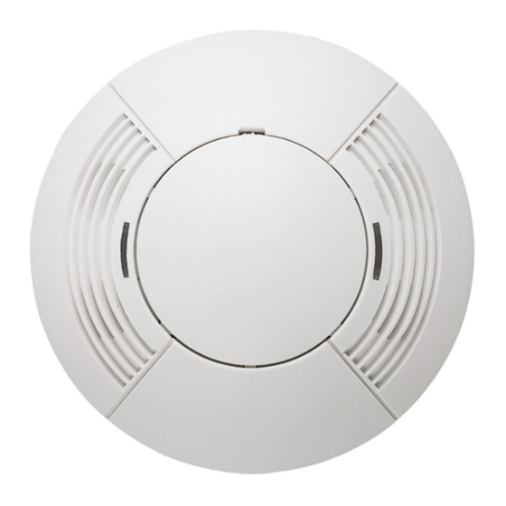
The LOS-C Series of ceiling-mounted sensors incorporate ultrasonics (CUS), infrared (CIR), and dual technologies
(CDT). They integrate into Lutron systems or function as stand-alone controls using a Lutron power pack.
FEATURES
• Intelligent, continually adapting sensors
• 20-24V
, Class 2 (PELV) low voltage, 33 mA nominal
• 450 to 2000 sq.ft. coverage, as indicated in model number (when mounted on 8 ft. ceiling)
• Second dry contact closure available on R models
• LED indicators: Ultrasonic (US)-green, Infrared (IR)-red, Dual Tech (DT)-red and green
• For indoor use only
COVERAGE AND PLACEMENT
• The occupant sensor must have an unobstructed view of the room. Do not mount behind or near tall cabinets,
shelves, hanging fixtures, etc.
• Keep the occupant sensor away from air flow.
• If installing a 180° occupant sensor, place the sensor on the same wall as the doorway so that hallway traffic will not
affect the sensor; otherwise, place in center of room.
Load
• Closely follow the diagrams for major and minor motion coverage.
• Decrease total coverage area by 15% for "soft" rooms (for example, heavy draperies or heavy carpeting).
• Indicated range is when unit is mounted on an 8 ft. ceiling.
Black
White
Load
Red
Red
Model
US Minor Dims.
CUS-500*
16 x 16 (4.9 x 4.9)
CUS-1000*
23 x 23 (7.0 x 7.0)
CUS-2000**
23 x 45 (7.0 x 13.7)
CIR-450**
NA
CIR-1500**
NA
CDT-500*
23 x 16 (7.0 x 4.9)
CDT-1000*
23 x 23 (7.0 x 7.0)
CDT-2000**
23 x 45 (7.0 x 13.7)
*180° field of view
**360° field of view
LOS-CUS-500/1000/2000
LOS-CIR-450/1500
LOS-CDT-500/500R/1000/1000R/2000/2000R
Please Read
Class 2 (PELV) Devices
Motion Detection Ranges
US Major Motion
US Minor Motion
US
Minor
Motion
IR Minor Motion
IR Major Motion
Dimensions and Ranges are in feet (m).
US Major Dims.
IR Minor
22 x 22 (6.7 x 6.7)
NA
32 x 32 (9.8 x 9.8)
NA
32 x 64 (9.8 x 19.5)
NA
NA
6.5 (1.9)
NA
12 (3.7)
32 x 22 (9.8 x 6.7)
12 (3.7)
32 x 32 (9.8 x 9.8)
12 (3.7)
32 x 64 (9.8 x 19.5)
12 (3.7)
R
US
Major
Motion
IR Major
NA
NA
NA
12 (3.7)
22 (6.7)
22 (6.7)
22 (6.7)
22 (6.7)
Advertisement

Summary of Contents for Lutron Electronics LOS-C Series
- Page 1 Red (+20-24 V The LOS-C Series of ceiling-mounted sensors incorporate ultrasonics (CUS), infrared (CIR), and dual technologies Red (+20-24 V (CDT). They integrate into Lutron systems or function as stand-alone controls using a Lutron power pack.
- Page 2 PRE-INSTALLATION SENSOR ADJUSTMENTS 1. For installation by a qualified electrician in accordance with national and local codes and the following instructions. Timer Test Mode Factory Settings 2. For indoor use only. 1. Remove the retainer cover. 3. CAUTION: RISK OF ELECTRIC SHOCK. Disconnect power before installing. Never wire energized electrical 2.


