
Subscribe to Our Youtube Channel
Related Manuals for Siemens LU-180


Summary of Contents for Siemens LU-180
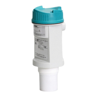
- Page 1 Ultrasonic Transmitters LU-180 (Sitrans LU-180) Operating Instructions Edition 06/2016...
- Page 2 ___________________ SITRANS LU180 Introduction ___________________ Description ___________________ Installing and mounting ___________________ Connecting Ultrasonic Transmitters SITRANS LU180 ___________________ Commissioning ___________________ Operating Operating Instructions ___________________ Troubleshooting ___________________ Technical data ___________________ Appendix 06/2016 A5E37100674-AA...
- Page 3 Note the following: WARNING Siemens products may only be used for the applications described in the catalog and in the relevant technical documentation. If products and components from other manufacturers are used, these must be recommended or approved by Siemens. Proper transport, storage, installation, assembly, commissioning, operation and maintenance are required to ensure that the products operate safely and without any problems.
-
Page 4: Table Of Contents
Table of contents Introduction ..............................5 Description ..............................7 Installing and mounting ..........................9 Environmental ........................... 9 Location ............................ 9 Threaded ..........................10 Flange adapter (optional) ......................11 4" Sanitary ..........................12 LU180 with FMS200 mounting bracket................... 15 Connecting .............................. 17 Connecting the LU180 ...................... - Page 5 Table of contents Fail-safe ..........................32 6.10 Adjusting the fail-safe setting ....................32 6.11 Fail-safe timer ........................33 6.12 Adjusting the fail-safe timer ....................33 6.13 Units ............................33 6.14 Adjusting the units ........................34 Troubleshooting ............................35 Technical data ............................37 Power .............................
-
Page 6: Introduction
Please note the following: • The user is responsible for all changes and repairs made to the device. • All new components must be provided by Siemens. • Restrict repair to faulty components only. • Do not re-use faulty components. - Page 7 Introduction SITRANS LU180 Operating Instructions, 06/2016, A5E37100674-AA...
-
Page 8: Description
The echo is processed by the SITRANS LU180 using Siemens' proven ‘Sonic Intelligence’ techniques. Filtering is applied to help discriminate between the true echo from the material, and false echoes from acoustical and electrical noises and agitator blades in motion. - Page 9 Description SITRANS LU180 Operating Instructions, 06/2016, A5E37100674-AA...
-
Page 10: Installing And Mounting
Installing and mounting Environmental The SITRANS LU180 should be mounted in an area that is within the temperature range specified, and that is suitable to the housing rating and materials of construction. It is advisable to keep the device away from high voltage or current runs, contactors and SCR control drives. -
Page 11: Threaded
Installing and mounting 3.3 Threaded Threaded ① Electronics ② Mounting thread ③ Sensor The SITRANS LU180 is available in three thread types: 1. 2" NPT ((Taper), ANSI/ASME B1.20.1) 2. R 2" ((BSPT), EN 10226) 3. G 2" ((BSPP), EN ISO 228-1 Note Before inserting the SITRANS LU180 into its mounting hole, ensure that the threads are of the same type to avoid damaging the device. -
Page 12: Flange Adapter (Optional)
Installing and mounting 3.4 Flange adapter (optional) Flange adapter (optional) The SITRANS LU180 can be fitted with the optional 75 mm (3") flange adapter for mating to 3" ANSI, DIN 65PN10 and JIS 10K3B flanges. ① SITRANS LU180 ② Optional flange adapter (2" NPT - 7ML1830-1BT, 2" BSPT - 7ML1830-1BU) SITRANS LU180 Operating Instructions, 06/2016, A5E37100674-AA... -
Page 13: 4" Sanitary
Installing and mounting 3.5 4" Sanitary 4" Sanitary Note • The sanitary version is suitable for chemical clean-in-place applications to 60 °C (140 °F) only. Ensure your cleaning chemicals are compatible with PVDF. ① Electronics ② Mounting flange ③ Sensor Mounting the sanitary version 1. - Page 14 Installing and mounting 3.5 4" Sanitary ① ④ SITRANS LU180 Ferrule ② ⑤ Clamp Tank ③ Adjusting wing nut SITRANS LU180 Operating Instructions, 06/2016, A5E37100674-AA...
- Page 15 Installing and mounting 3.5 4" Sanitary 4" Sanitary ferrule Note The inside of sanitary ferrule must be smooth, and free of burrs, seams or ridges. SITRANS LU180 Operating Instructions, 06/2016, A5E37100674-AA...
-
Page 16: Lu180 With Fms200 Mounting Bracket
Installing and mounting 3.6 LU180 with FMS200 mounting bracket LU180 with FMS200 mounting bracket ① LU180 ② FMS200 mounting bracket (7ML1830-1BK) with 7ML1830-1DT (Locknut, 2" NPT) or 7ML1830- 1DQ (Locknut, 2" BSPT). SITRANS LU180 Operating Instructions, 06/2016, A5E37100674-AA... - Page 17 Installing and mounting 3.6 LU180 with FMS200 mounting bracket SITRANS LU180 Operating Instructions, 06/2016, A5E37100674-AA...
-
Page 18: Connecting
Connecting Connecting the LU180 4.1.1 Cable entry 1. Loosen lid and remove it. 2. Install cable gland or conduit. 3. Insert wires through gland or conduit and up through cable guide. 4. Connect wiring. 5. Replace lid and tighten it. * Lid removed for clarity SITRANS LU180 Operating Instructions, 06/2016, A5E37100674-AA... -
Page 19: System Diagram
Connecting 4.1 Connecting the LU180 Note • To maintain IP and NEMA ratings, tighten the lid between 4 to 4.5 Nm. • Ensure the cable gland is screwed in to the enclosure tightly and the cable is within the specified clamping range (6.5 to 12 mm). •... -
Page 20: Instructions Specific To Hazardous Area Installations
Connecting 4.2 Instructions specific to hazardous area installations Instructions specific to hazardous area installations Instructions specific to hazardous area installations (in accordance with IEC 60079-0:2011 clause 30) The following instructions relevant to safe use in a hazardous area apply to equipment covered by certificate numbers Sira 15ATEX2334X and IECEx SIR 15.0118X. -
Page 21: Nameplates For Hazardous Area Installations
ATEX certificate on nameplate The ATEX certificate listed on the nameplate can be downloaded from the LU180 product page on our website http:wwww.siemens.com/SITRANSLU180. Go to Support > Approvals > Certificates. The IECEX certificate listed on the nameplate can be viewed on the IECEx website: 1. - Page 22 Connecting 4.3 Nameplates for hazardous area installations SITRANS LU180 Operating Instructions, 06/2016, A5E37100674-AA...
- Page 23 Connecting 4.3 Nameplates for hazardous area installations SITRANS LU180 Operating Instructions, 06/2016, A5E37100674-AA...
-
Page 24: Commissioning
Commissioning Start up 1. With the SITRANS LU180 correctly installed (or aimed at a wall 0.25 to 5 m away), apply power. The device starts up, displaying the following: ① ⑤ '4' key Units ② ⑥ '20' key LOE/fault ③ ⑦... -
Page 25: Calibration
Commissioning 5.2 Calibration Calibration The calibration of the mA output may be done such that its span will be either proportional or inversely proportional to the material level. Note The 4 and 20 mA levels may be calibrated in any order. Proportional span Inversely proportional span high level = 20 mA... -
Page 26: Ma Calibration
Commissioning 5.4 4 mA calibration 4 mA calibration Press "4" Press "4" again 4 mA calibration calibration invalid if new 4 mA calibration retry 20 mA calibration Press "20" Press "20" again 20 mA calibration calibration invalid if new 20 mA calibration retry Note Calibration bypasses the measurement response rate. -
Page 27: Operation Status
Commissioning 5.6 Operation status Operation status The graphic portion of the display gives the user a visual indication of the SITRANS LU180 operating status. During commissioning, viewing the graphic can assist the user in properly locating and installing the unit to achieve optimum performance. ①... -
Page 28: Operating
Operating Adjustments There are several operating adjustments that can be made to the SITRANS LU180. To access the operating adjustments, simultaneously press the "4" and "20" keys until the desired adjustment is obtained. A viewing sequence of the stored value is automatically initiated. During this time the value can be changed by pressing either the "4"... -
Page 29: Calibration, Scrolling Method
Operating 6.2 Calibration, scrolling method Calibration, scrolling method The 4 and 20 mA calibration values can be selected where reference levels, either from the material in the vessel or from a target, cannot be provided. This method can also be used to trim the output levels obtained by the Calibration: reference method (Page 24) To change the stored calibration value, obtain the 'c 4' or 'c 20' display. -
Page 30: 20 Ma Calibration
Operating 6.4 20 mA calibration 20 mA calibration 20 mA calibration initiated view stored 20 mA calibration value (i.e. 0.50 m) press ”4” to increase to new calibration value (i.e. 0.45 m) new calibration value Blanking Blanking is used to ignore the zone in front of the transducer where false echoes are at a level that interfere with the processing of the true echo. -
Page 31: Adjusting The Blanking Value
Operating 6.6 Adjusting the blanking value Adjusting the blanking value To change the stored blanking value, go to the 'bL' display (as described in Adjustments (Page 27)), and proceed as follows: 1. Press the "20" key to increase the blanking value, or the "4" key to decrease it until the correct value is displayed. -
Page 32: Adjusting The Speed Of Response
Operating 6.8 Adjusting the speed of response filter: discriminates between false echoes from acoustical and electrical noise, and the material (target) surface. fail-safe timer: establishes the 'Waiting' period from the time a loss of echo or operating fault condition starts, until the fail-safe default is effect- ed. -
Page 33: Fail-Safe
Operating 6.9 Fail-safe Fail-safe In the event a loss of echo or fault condition exceeds the 'Waiting' period (see Speed of response (Page 30), or Fail-safe timer (Page 33)), the '?' icon appears and one of the following fail-safe defaults is immediately effected. default reading full... -
Page 34: Fail-Safe Timer
Operating 6.11 Fail-safe timer 6.11 Fail-safe timer The fail-safe timer allows the user to vary the ‘waiting’ period from the time a loss of echo or operating fault condition begins, until the fail-safe default is effected. The ‘waiting’ period is adjustable from 1 to 15 minutes, in 1 minute increments. -
Page 35: Adjusting The Units
Operating 6.14 Adjusting the units 6.14 Adjusting the units To change the units, go to the 'Un'' display (as described in Adjustments (Page 27)), and proceed as follows: 1. Press the "20" key to scroll forward through the available options (1-2), and press the "4" key to scroll backwards. -
Page 36: Troubleshooting
Troubleshooting The echo is not reliable and the LU180 is waiting for a valid echo before updating the measurement. Probable causes are: • Material or object in contact with sensor face • The LU180 is too close to the fill point •... - Page 37 Troubleshooting SITRANS LU180 Operating Instructions, 06/2016, A5E37100674-AA...
-
Page 38: Technical Data
Technical data Note Siemens makes every attempt to ensure the accuracy of these specifications but reserves the right to change them at any time. Power 12 to 30 V DC (at terminal blocks), 0.1 A surge loop current 4 to 20 mA max... -
Page 39: Outputs
Technical data 8.4 Outputs Outputs mA output Range 4 to 20 mA Span proportional or inversely proportional Accuracy 0.25% of full scale at reference conditions Resolution 3 mm (0.125") Loading 600 ohms max loop load at 24 V DC supply Cable twisted pair, AWG 28 to 16 (0.34 to 1.5 mm) or equivalent Construction... -
Page 40: Approvals
Technical data 8.7 Approvals Approvals General purpose CSAus/c, CE, Hazardous Intrinsically safe IECEx Ex ia IIC T4 Ga ATEX II 1G Ex ia IIC T4 Ga FM/CSA Class I, II, III, Div. 1, Groups A,B,C,D,E,F,G T4 KCC-REM-S49 SITRANS LU180 Operating Instructions, 06/2016, A5E37100674-AA... - Page 41 Technical data 8.7 Approvals SITRANS LU180 Operating Instructions, 06/2016, A5E37100674-AA...
-
Page 42: Appendix
Appendix Measurement interval ① Interval (in seconds) ② mA loop current SITRANS LU180 Operating Instructions, 06/2016, A5E37100674-AA... - Page 43 Appendix A.1 Measurement interval SITRANS LU180 Operating Instructions, 06/2016, A5E37100674-AA...
- Page 44 For more information www.siemens.com/level www.siemens.com/weighing Siemens Canada Limited 1954 Technology Drive Printed in Canada P.O. Box 4225 Subject to change without prior notice Peterborough, ON A5E37100674 Rev. AA Canada K9J 7B1 © Siemens AG 2016 www.siemens.com/processautomation...
Need help?
Do you have a question about the LU-180 and is the answer not in the manual?
Questions and answers