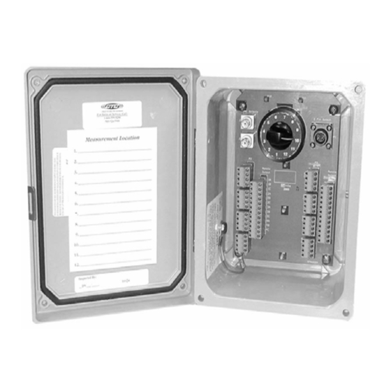
Summary of Contents for CTC Union SB142
- Page 1 Product Manual MNX10015 / REV C MODEL SB142, SB242 Dual Output Series Switch Boxes...
-
Page 2: Table Of Contents
Contents Section I Overview Introduction..............………….… 2 Description..................2 Section II Installation Mounting……….................. 3 Electrical Connections................ 6 Section III Maintenance General..................... 11 Warranty................... 12 Figures Figure 1 (Dual Output Switch Box Layout)......... 3 Figure 2 (Mounting Bracket Placement)..........4 Figure 3 (Conduit Entry for Switch Box)..........4 Figure 4 (Ground Wire Placement)............. -
Page 3: Section I
Introduction This document contains information on the operation, installation and maintenance of the SB142/SB242 Dual Output Switch Boxes. This manual is an overview of the system and references the specific component manuals. User manuals are provided with the system for all configurable internal components. -
Page 4: Installation
Section II Installation Mounting Steps Note: The term “Sensor” used in the notes below, refers to vibration sensors. An accelerometer is a type of vibration sensor and can therefore be used whenever sensor is referenced. Portable Data Collector Access Points BNC-J1 for Measurement Point A 2 Pin Output BNC-J2 for Measurement Point C... -
Page 5: Mounting
1. For SB142 Series Switch Boxes (Fiberglass Enclosure): Attach the enclosed mounting brackets to the Switch Box at the pre-determined locations (SB242 Series Switch Boxes {Stainless Steel} are supplied with mounting brackets attached) Note: If you have purchased a switch box without cable entries provided, you should add your own entry prior to mounting the switch box. - Page 6 3. Grounding of the Switch Box: Ensure the shield ground wire on the SB142 Series Switch Boxes (Fiberglass Enclosures) is connected to earth ground. Note: The SB242 Series Switch Boxes (Stainless Steel Enclosures) are internally grounded to the enclosure. Note: For SB142 Series Fiberglass Enclosure, customer is required to supply wire from ground to shield ground lug, located on the outside of the enclosure .
- Page 7 4. Installation of Sensor/Signal Input Cable: Run sensor/signal input cable to the location of the switch box. Ensure the correct amount of cable is allocated. Splicing cable is not recommended. Note: For conduit installations, conduit would be run to the switch box prior to completion of Step 4.
- Page 8 Figure 8. Bottom View for Cord Grip Installations For SB142 and SB242 Series, attach sensor/signal input cables as follows: a. Strip outer jacket of cable back 1 ¼”-1 1/2” and remove all of the shielding. b. Strip red, black, and (white) insulation back ¼” ( Please Note for Biaxial sensor you will strip green, black and white conductors omitting red conductor refer to figure 9A).
- Page 9 Temperature and Dynamic Acceleration: (Figure 9) a. Socket A – Positive (+ RED) connection for the dynamic acceleration and with output on the BNC “J1” and the (2) pin Output connectors. b. Socket B – Negative (- BLACK) connection for the dynamic acceleration and volt output for temperature.
- Page 10 Dual Vibration with 4-20mA output and Dynamic outputs: (Figure 9B) a. Socket A – Positive (+ WHITE) connection for the dynamic acceleration and would output on the BNC “J1” and the (2) pin MIL output connectors. b. Socket B – Negative (- BLACK) connection for the dynamic acceleration and 4-20mA velocity output.
-
Page 11: Figure 10. Connecting Cables To Enclosure
5. Identification of inputs: Mark the Measurement Location Card with a description of each SENSOR location. Repeat these steps until all cables have been wired into their respective Channel Location on the terminal strips Figure 10. Connecting Figure 11. Connecting Cables to Enclosure Cables to Enclosure If Cord Grips are used, ensure cord grip covers are securely fastened to base. - Page 12 Post-Installation Procedures: 1. Utilizing TM1018 Accelerometer Verification Meter (Figure 12), cable conductivity, sensor location and proper wiring connections can be verified. The Verification Meter will indicate if the sensor, cable and/or junction box is in working condition. It will also confirm bias voltage of the accelerometer, which will inform you of the operation of the internal accelerometer amplifier.
-
Page 13: Maintenance
- Short Circuit. Indicates one of the following: a. Water or contamination in the connector b. Reverse Wiring ((+) and (-) leads are reversed) a. Wires in switch box or cable connector (+) & (-) are touching Section III Maintenance General There are no customer replaceable parts.


Need help?
Do you have a question about the SB142 and is the answer not in the manual?
Questions and answers